

Hot-pipe temperature measuring device
A heat pipe and measurement technology, applied in the field of heat transfer, can solve the problems of the actual temperature error of the heat pipe surface in the measurement results, the heat-resistant tape is not easy to apply force, the contact is not direct, reliable, etc., to reduce errors, improve accuracy, Effect of reducing thermal resistance
- Summary
- Abstract
- Description
- Claims
- Application Information
AI Technical Summary
Problems solved by technology
Method used
Image

Examples
Embodiment Construction
[0014] The present invention will be described in further detail below in conjunction with the accompanying drawings.
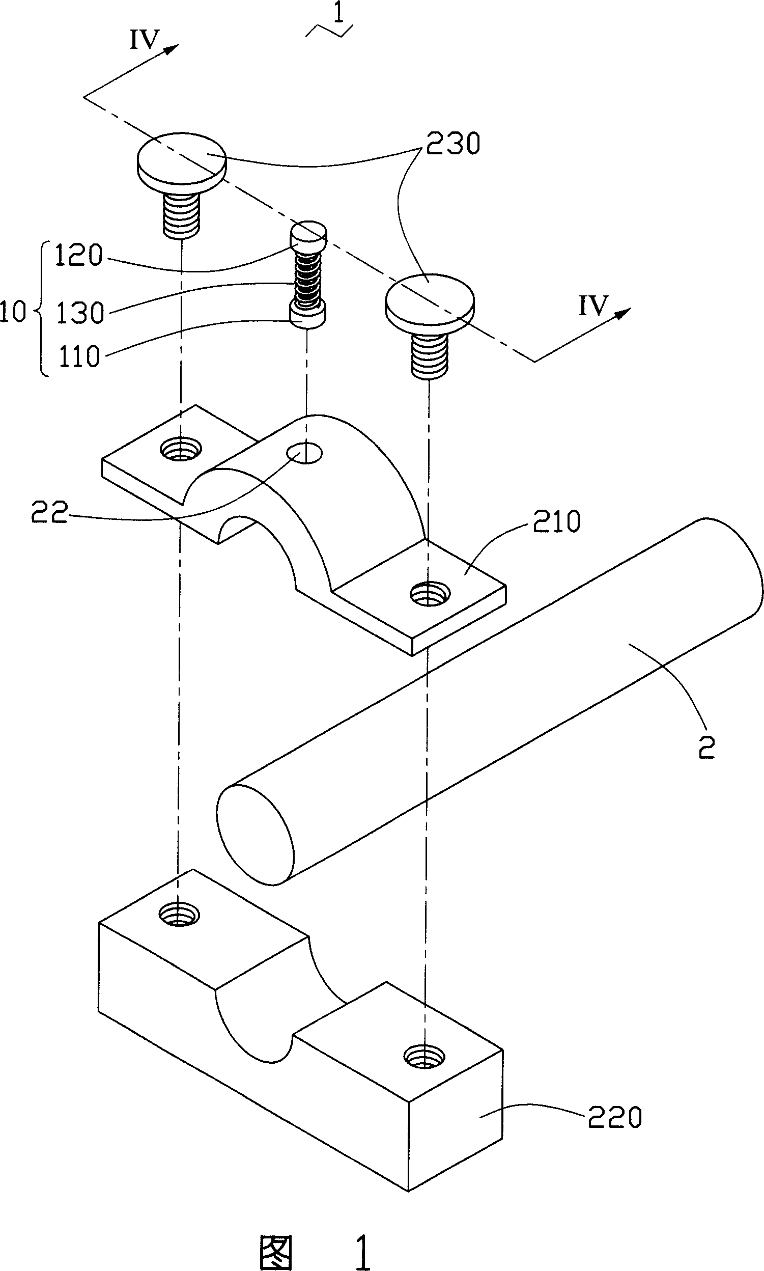
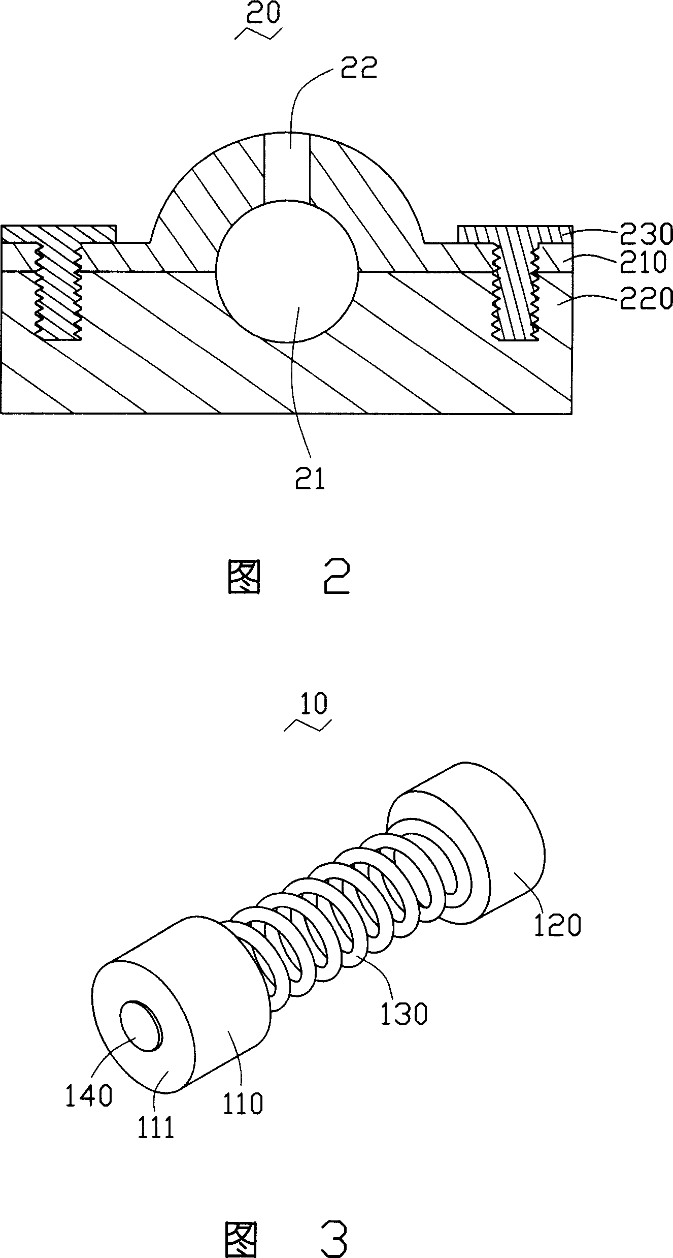
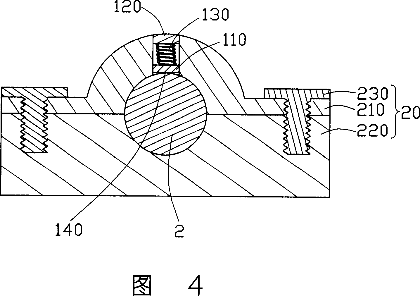
[0015] Please refer to Fig. 1 to Fig. 4 together, the heat pipe temperature measuring device 1 provided by the present invention includes: a clamping part 20 and a measuring assembly 10, and the clamping part 20 is provided with an accommodating cavity 21 and a The accommodating cavity 21 communicates with the insertion hole 22, the accommodating cavity 21 is used to clamp the heat pipe 2, and the insertion hole 22 is used to insert the measurement assembly 10, the measurement assembly 10 includes: a bearing block 110, A pressing block 120, a spring 130 and a thermocouple 140, the spring 130 is supported between the bearing block 110 and the pressing block 120, and the thermocouple 140 is attached to a side of the bearing block 110 away from the spring 130 The surface 111 is used to abut against the heat pipe 2 so as to measure the temperature of the heat pip...
PUM
 Abstract
Description
Claims
Application Information