Antenna device for base station and method for networking and expansion

A technology of antenna device and base station, applied in the field of antenna device of base station

Inactive Publication Date: 2011-01-12
HUAWEI TECH CO LTD
View PDF4 Cites 0 Cited by
  • Summary
  • Abstract
  • Description
  • Claims
  • Application Information

AI Technical Summary

Problems solved by technology

[0013] The purpose of the present invention is to address the deficiencies of the prior art and propose a base station antenna device to solve the problem of difficult expansion of the existing wireless cellular network

Method used


Image

  • Antenna device for base station and method for networking and expansion
  • Antenna device for base station and method for networking and expansion
  • Antenna device for base station and method for networking and expansion

Examples


Embodiment 1

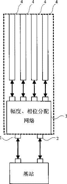
[0047] image 3 It is a structure diagram of Embodiment 1 of an antenna device of a base station according to the present invention. The device is connected to the base station through a left joint 1 and a right joint 2, and also includes: an amplitude phase distribution network 3, which is used to convert the signal of the base station to a designed amplitude The sum and phase are distributed to the antenna array; the split antenna 4 of the four-column antenna array is used for transmitting and receiving signals. The signal output from the left connector 1 or the right connector 2 passes through the amplitude and phase distribution network 3 to generate 4 outputs, which are connected to the antenna array 4 respectively.

[0048] Among them, the structure of the amplitude phase distribution network 3 is as follows Figure 4 shown, including:

[0049] Two one-layer 3 decibel 90-degree electric bridges 51 and 52 are used to divide one input signal into two outputs equally, and...

Embodiment 2

[0057] In this embodiment, the antenna structure is the same as that in Embodiment 1, and the structure of the amplitude and phase distribution network 3 is as follows Figure 5 shown, including:

[0058] Two 7.7 decibel couplers 111 and 112 are used to divide one input signal into two outputs, and the difference between the two output signals is 7.7 decibels;

[0059] Two 180-degree phase shifters 121 and 122 are used to output the phase of one output signal of the 7.7 decibel coupler after 180 degrees;

[0060] Two 3dB 90-degree bridges 131 and 132 are used to split the two input signals into two outputs respectively, the phase difference of the two output signals is 90 degrees, and the output signals are output through the four-column antenna array.

[0061] The function of the amplitude and phase distribution network in this embodiment is the same as that of the corresponding part in the first embodiment, but compared with the first embodiment, the amplitude and phase dis...


PUM


Abstract

The invention is concerned with antenna device of base station. It relates to left tie-in and right tie-in and it connects with base station through left and right tie-ins. Range phase allocation network distributes signal of base station to each unit of antenna array as designed range and phase. The antenna of even antenna array sends and accepts signal. It also opens a kind of networking and enlarging capability method of antenna device. Left and right tie-ins connect with base station by a divider and the power of signal to base station are deuced by this divider, during the networking process. During the enlarging of network, two ways of import signal of base station enter into antenna device through left and right tin-ins. During the enlarging process, this invention carried smooth enlarging and reduces the workload and complexity without increasing amount of address of base station and adjusting direction of antenna. It increases the cover range of base station during networkingand reduces amount of base station and cover cost.

Description

technical field [0001] The invention relates to antenna technology, in particular to an antenna device of a base station, and a method for network formation and capacity expansion using the base station with the antenna structure. Background technique [0002] The mobile communication system is covered by many base stations (BTS) to cover the service area. The existing base station antenna has a single column antenna, and there is only a feed network in the vertical direction, but there is no feed network in the horizontal direction. The pattern is approximate A regular hexagon, the base station using this antenna has a coverage area like a cell, so it is also called a "cellular system". A mobile communication system has a lot of cells, so the network investment cost is very high, usually ranging from tens of billions to hundreds of billions. Obviously, if the area covered by each base station is larger (that is, the cell area is larger), the number of base stations will be...

Claims


Application Information

Patent Timeline
Patent Type & Authority Patents(China)
IPC IPC(8): H04B7/04H04W16/02H04W88/08
Inventor 李亚锐蒋金弟应关祥
Owner HUAWEI TECH CO LTD
Why Eureka
Try Eureka