Workflow optimization for high thoughput imaging enviroments

An imaging system and image technology, applied in electrical digital data processing, special data processing applications, medical images, etc., to achieve the effects of improving patient throughput, optimizing scanning protocols, and being easy to use

Active Publication Date: 2015-05-27
KONINKLIJKE PHILIPS ELECTRONICS NV
View PDF5 Cites 0 Cited by
  • Summary
  • Abstract
  • Description
  • Claims
  • Application Information

AI Technical Summary

Problems solved by technology

Scanner captures patient images

Method used


Image

  • Workflow optimization for high thoughput imaging enviroments
  • Workflow optimization for high thoughput imaging enviroments
  • Workflow optimization for high thoughput imaging enviroments

Examples


Embodiment Construction

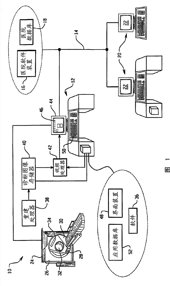
[0044] refer to figure 1 , the operation of the imaging system 10 is controlled by an operator workstation 12 coupled to a hospital network 14 . Hospital network 14 includes associated software devices 16 and hospital records database 18 . Workstation 12 may be hardwired to network 14 or communicate wirelessly therewith. In this manner, workstation 12 can communicate with other hospital workstations or computers or remote devices 20 connected to hospital network 14 so that images and patient records can be communicated to the appropriate medical personnel and displayed on associated monitors 22 .

[0045] Imaging system 10 generally includes a CT scanner 24 including a non-rotating gantry 26 . The X-ray tube 28 is mounted on a rotating gantry 30 . Aperture 32 defines the examination area of ​​CT scanner 24 . A radiation detector array 34 is mounted on the rotating gantry 30 to receive radiation from the X-ray tube 28 after traversing the examination region 32 . Alternativ...


PUM


Abstract

A medical diagnostic imaging system (10) is coupled to a hospital network (14) to optimize a throughput of a scanner (24). The hospital network includes a hospital records database (18) and a plurality of hospital computers and remote means (20). A workstation (12) is coupled to the scanner (24) and the hospital network (14) and is used to control a scanning process. The workstation (12) includes a display (44), an applications database (52), which is configurable by a user, and an interface means (48) for displaying interactive user interface screens (46) on the display (44). The interface screens (46) allow the user to configure the applications database (52) and interactively control the scanning process.

Description

technical field [0001] The present invention relates to diagnostic imaging systems and methods. The present invention is particularly useful for increasing the throughput of CT scanners and other diagnostic equipment, and will be described with particular reference to the above applications. However, it is understood that the present invention is also applicable to improving medical treatment efficiency, diagnosis efficiency, and the like. Background technique [0002] Multi-slice CT (MSCT) imaging has achieved major technological breakthroughs in a very short period of time. Sixteen-slice CT quickly became a widely used device in radiology, ET, and trauma departments. MSCT technology not only enables the acquisition of a large number of CT slices on a routine basis, but also enables the use of CT to diagnose non-traditional anatomical structures, such as cardiac vessels. The emergence of MSCT has made it possible to diagnose diseases at an early, treatable stage by routi...

Claims


Application Information

Patent Timeline
Patent Type & Authority Patents(China)
IPC IPC(8): G06F19/00A61B6/00A61B6/03
CPCA61B6/00A61B6/032A61B6/4085A61B6/465A61B6/467A61B6/469A61B6/563A61B6/566G16H40/63G16H30/20G16H30/40
Inventor S·戈特曼S·罗森伯格R·本-塔尔S·桑亚-戈帕尔J·S·杜尔甘
Owner KONINKLIJKE PHILIPS ELECTRONICS NV
Why Eureka
Try Eureka