Voltage regulator

A technology of voltage adjustment and voltage regulator, which is applied in the direction of adjusting electrical variables, control/regulation systems, instruments, etc. It can solve the problems of fast transient response speed and low power consumption of voltage adjustment devices at the same time, so as to improve performance, The effect of low power consumption and guaranteed transient characteristics

Active Publication Date: 2007-06-27
CHIPSEA TECH SHENZHEN CO LTD
View PDF3 Cites 20 Cited by
  • Summary
  • Abstract
  • Description
  • Claims
  • Application Information

AI Technical Summary

Problems solved by technology

[0009] The purpose of the present invention is to provide a voltage adjustment device to solve the problem that the voltage adjustment device in the prior art cannot simultaneously take into account low power consumption, fast transient response speed, stability and simple application

Method used


Image

  • Voltage regulator
  • Voltage regulator
  • Voltage regulator

Examples


Embodiment Construction

[0028] The present invention will be further described in detail below in conjunction with the accompanying drawings and specific embodiments.

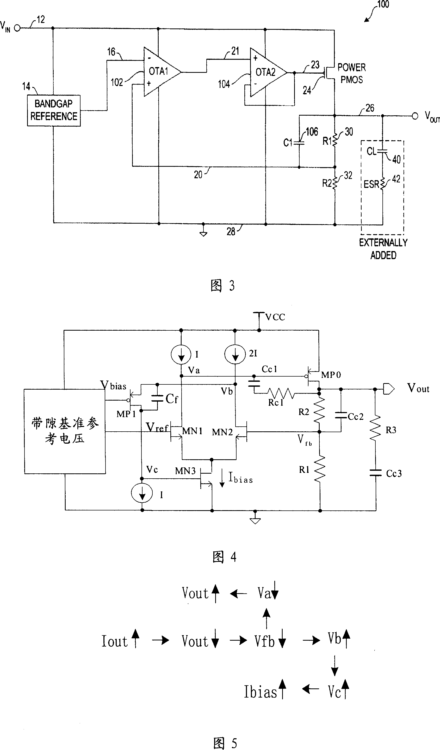
[0029] As shown in Figure 4, the technical solution of this embodiment includes a bandgap reference voltage source, an output voltage detection and feedback unit, an automatic current bias circuit, an integrated frequency compensation circuit, and a drive output circuit.

[0030] Instructions are given below:

[0031] Among them, the bandgap reference voltage source circuit belongs to the classic bandgap voltage generation circuit, and the bandgap reference voltage source provides the reference voltage V for the entire voltage regulator. ref , MP1 tube bias voltage V bias and current sources in the circuit.

[0032] As shown in Figure 4, the output voltage detection and feedback unit is composed of resistor R2, resistor R1, MOS transistor MN1, MOS transistor MN2, capacitor Cc2, MOS transistor MP1, and MOS transistor MN3, wherein the...


PUM


Abstract

The voltage adjuster includes band-gap reference voltage source, voltage detection and feed back unit, auto bias circuit, frequency compensation circuit, and driver output circuit. The reference voltage source generates reference voltage and bias current. The voltage detection and feed back unit detects voltage output from the voltage adjuster, and feeds back the output voltage to the auto bias circuit and the control circuit of the drive tube or controlling bias circuit and driving capability automatically. The frequency compensation circuit guarantees tolerance of phase in whole loop and speed of transient response of voltage adjuster to make steady operation, and quick transient response of adjuster close loop. Features are: very low own power consumption, wide operating range, realized by standard CMOS technique, simplified design of voltage adjuster effectively, and raised performance of adjuster.

Description

technical field [0001] The present invention relates to the field of power management and microelectronic technology, more specifically, to a voltage regulator. Background technique [0002] Chip design often encounters the problem that the external power supply voltage is higher than the working voltage of the internal circuit of the chip. The solution to this problem is to integrate a voltage regulator inside the chip to adjust the internal working voltage of the chip to the required level. [0003] In the case of power management, the input signal is often an AC signal, such as 220V power frequency AC input. After the input voltage is rectified, it is input to the circuit board. At this time, the power supply voltage fluctuates greatly. Fluctuations in the power supply voltage can cause circuit malfunctions or other problems. The main function of the voltage regulator in power management occasions is to adjust the input voltage with large fluctuations to a stable voltage...

Claims


Application Information

Patent Timeline
Patent Type & Authority Applications(China)
IPC IPC(8): G05F1/56G05F1/565
Inventor 周命福万巍陈征宇王金琐
Owner CHIPSEA TECH SHENZHEN CO LTD
Why Eureka
Try Eureka