Self-powered CMOS piezoelectric vibration energy harvester

An energy harvester, piezoelectric vibration technology, applied in generators/motors, piezoelectric effect/electrostrictive or magnetostrictive motors, electrical energy storage systems, etc. It is impossible to complete the acquisition alone, the circuit is bulky, etc., to achieve the effect of reducing the on-voltage drop, reducing the on-resistance, and fewer peripheral components

Active Publication Date: 2015-09-16
NINGBO UNIV
View PDF6 Cites 3 Cited by
  • Summary
  • Abstract
  • Description
  • Claims
  • Application Information

AI Technical Summary

Problems solved by technology

[0005] Synchronous switch inductor circuit (P-SSHI) and series synchronous switch inductor circuit (S-SSHI) recover power is still greatly affected by the back-end capacitor voltage and load impedance; synchronous charge extraction circuit (SECE), double synchronous switch circuit ( DSSH), Enhanced Dual Synchronous Switch Inductance Recovery Circuit (ESSH) and Optimized Synchronous Charge Extraction Circuit (OSECE) solve this problem. It is very advantageous, but the actual implementation is either too complicated, or its own circuit cannot complete the acquisition alone, and needs to be powered by an external power supply, or the circuit is large in size and difficult to integrate due to the need for more discrete components, so it is difficult to promote

Method used


Image

  • Self-powered CMOS piezoelectric vibration energy harvester
  • Self-powered CMOS piezoelectric vibration energy harvester

Examples


Embodiment Construction

[0012] The present invention will be further described in detail below in conjunction with the accompanying drawings and embodiments.

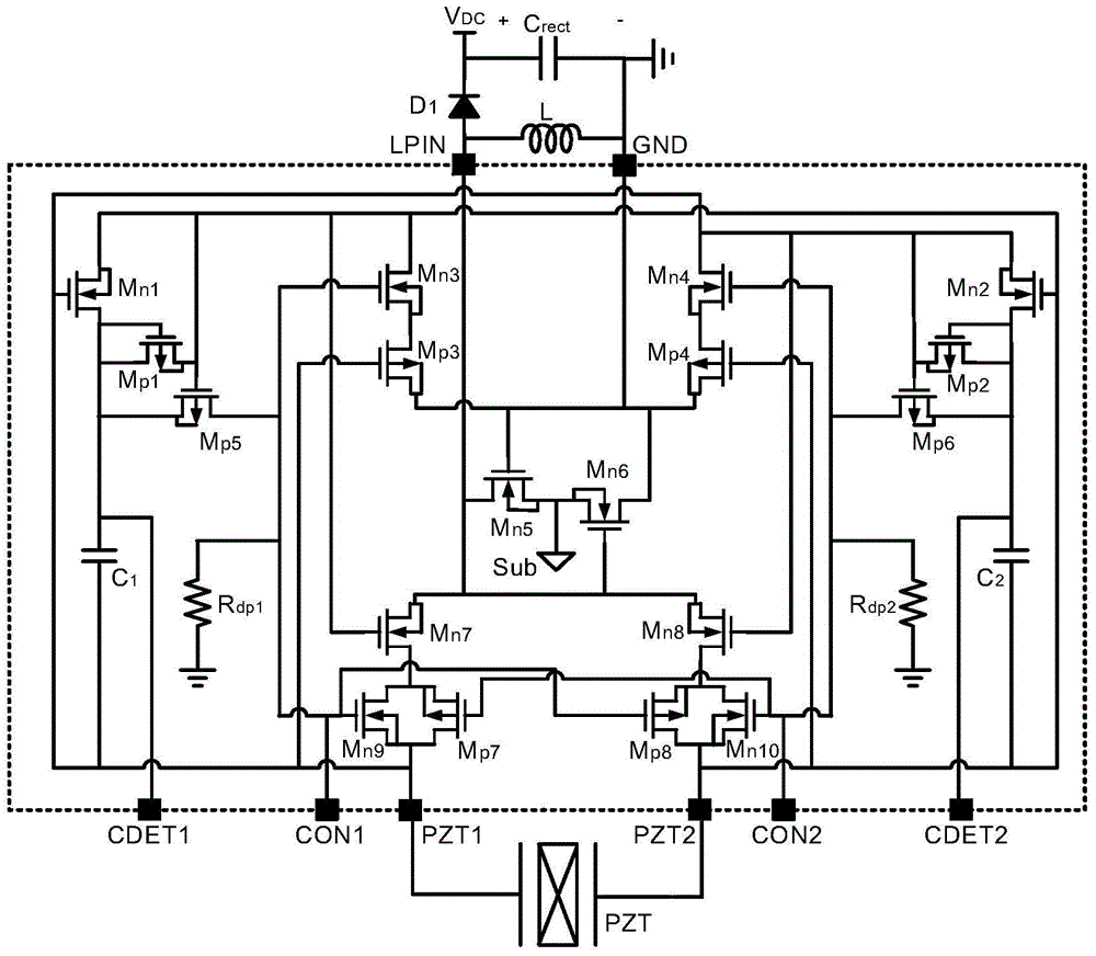
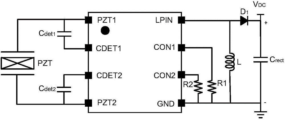
[0013] A self-powered CMOS piezoelectric vibration energy harvester, including a CMOS piezoelectric synchronous charge extraction acquisition interface circuit and a freewheeling energy storage circuit, the CMOS piezoelectric synchronous charge extraction acquisition interface circuit is packaged in the form of an integrated circuit, and the CMOS piezoelectric synchronous charge extraction The acquisition interface circuit is provided with the output control interface CON1 of the first detection circuit, the output control interface CON2 of the second detection circuit, the first piezoelectric element connection interface PZT1, the second piezoelectric element connection interface PZT2, the first capacitance detection interface CDET1, the second piezoelectric element connection interface Two capacitance detection interface CDET2, external induc...


PUM


Abstract

The invention discloses a self-powered CMOS piezoelectric vibration energy harvester. The self-powered CMOS piezoelectric vibration energy harvester is characterized in that the self-powered CMOS piezoelectric vibration energy harvester includes a CMOS piezoelectric synchronous charge extraction and collection interface circuit and a follow current energy storage circuit; the CMOS piezoelectric synchronous charge extraction and collection interface circuit is encapsulated in the form of an integrated circuit form; the CMOS piezoelectric synchronous charge extraction and collection interface circuit is provided with a first detection circuit output control interface, a second detection circuit output control interface, a first piezoelectric element connection interface, a second piezoelectric element connection interface, a first capacitance detection interface, a second capacitance detection interface, an external-connection inductance interface and a grounding port; the CMOS piezoelectric synchronous charge extraction and collection interface circuit includes a positive extremum detection module, a negative extremum detection module, a positive and negative extremum interlock switch, a positive and negative direction vibration automatic switching switch and a dynamic substrate level selection module. The self-powered CMOS piezoelectric vibration energy harvester has the advantages of easiness in integration, small circuit size, low power consumption and high energy extraction efficiency; and a self-powered design is adopted, so that the self-powered CMOS piezoelectric vibration energy harvester further has the advantage of no need for an external power source.

Description

technical field [0001] The invention relates to the technical field of integrated circuits, in particular to a self-powered CMOS piezoelectric vibration energy collector. Background technique [0002] Vibration energy exists in almost any environment, such as water, air flow in nature, vibration of industrial machines, vibration during operation of vehicles, human movement, even breathing, heartbeat, etc. Piezoelectric vibration energy harvesters use the positive piezoelectric effect of piezoelectric materials to convert vibration energy in the environment into electrical energy. Piezoelectric vibration energy harvesters have the advantages of high energy density, simple structure, long life, and easy integration, and are widely used in contemporary micro-power mobile and wearable electronic devices. [0003] Due to the vibration, the output voltage of the piezoelectric element is alternating, and the power supply of common microelectronic devices requires a stable DC volta...

Claims


Application Information

Patent Timeline
IPC IPC(8): H02N2/18H02J15/00
CPCY02E60/16
Inventor 施阁夏银水叶益迭钱利波阳媛屈凤霞
Owner NINGBO UNIV
Why Eureka
Try Eureka