

Inverter
A converter and current detector technology, applied in output power conversion devices, electronic commutators, conversion of AC power input to DC power output, etc., can solve the problems of increasing the number of components, complex software, and hindering miniaturization, etc. Achieve the effect of smooth current, improve low noise and vibration, and improve the freedom of configuration
- Summary
- Abstract
- Description
- Claims
- Application Information
AI Technical Summary
Problems solved by technology
Method used
Image

Examples
Embodiment approach 1
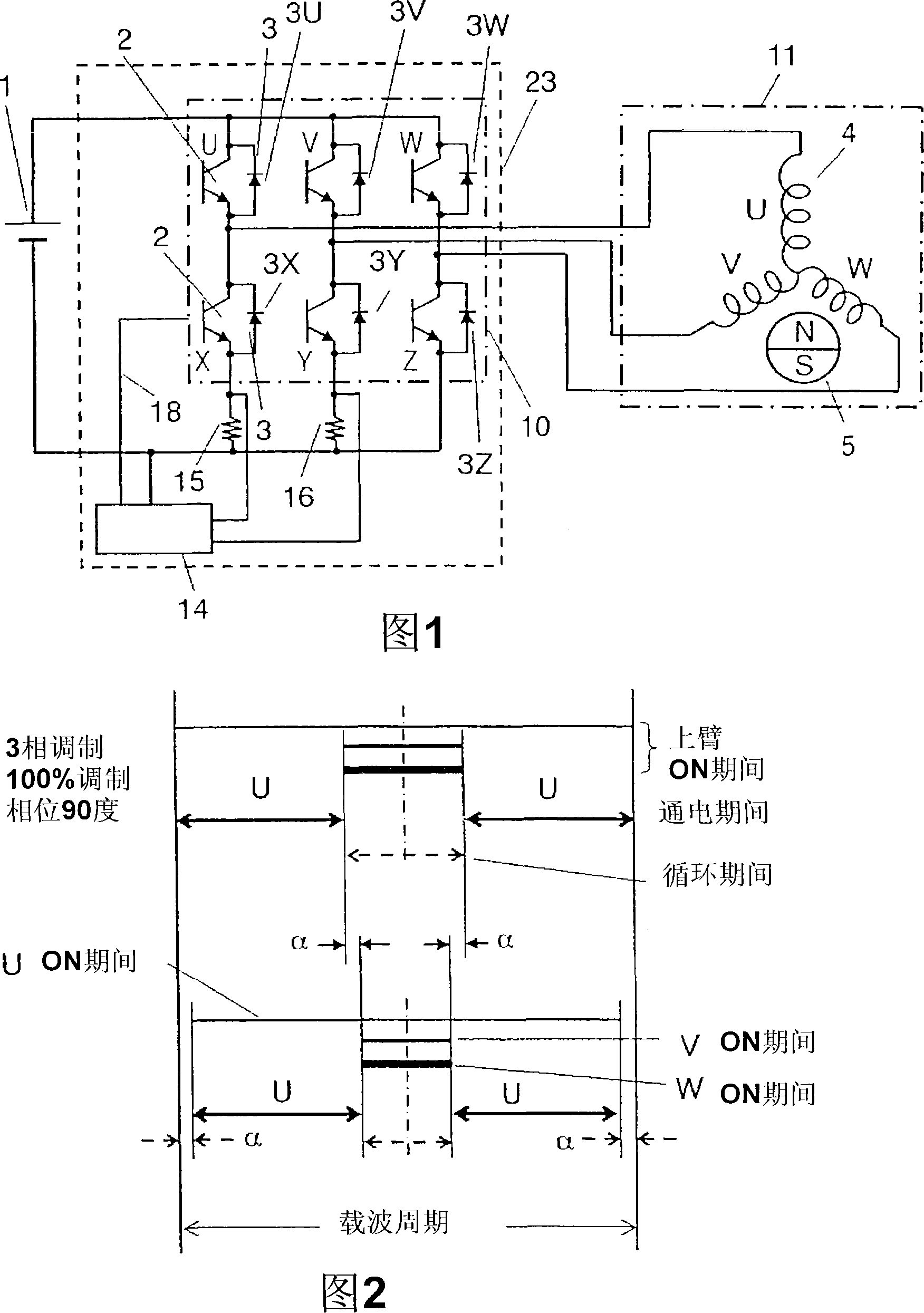
[0084] FIG. 1 is a diagram of an inverter device 23 and its peripheral circuits according to Embodiment 1 of the present invention. The difference from FIG. 22 in the background art is that there is no shunt resistor 17 , and the control circuit 13 becomes the control circuit 14 . Regarding other circuit units, the same as in FIG. 22 , the reference numerals and the like can be used as they are.
[0085] The control circuit 14 connects the upper arm switching elements U, V, W and the lower arm switching elements X, Y, Z through the connection line 18, and controls each switching element. When the switching element is an IGBT or a power MOSFET, it controls the gate voltage, and when it is a power transistor, it controls the base current.
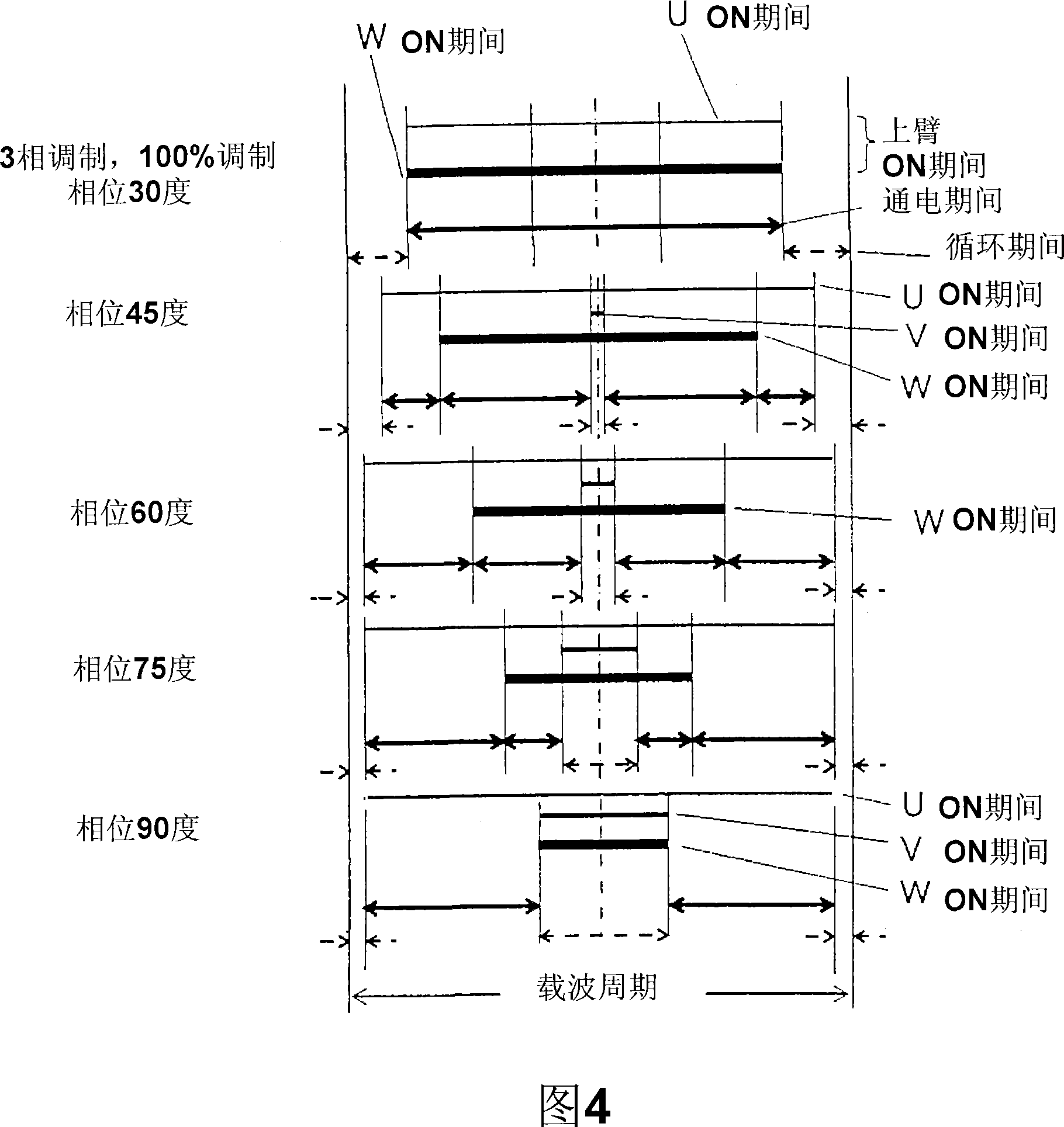
[0086] At a phase of 90 degrees in FIG. 24 , currents of only two phases (V phase, W phase) flow in the lower arm. Similarly, at the phase 210 degrees, only the U-phase and V-phase currents flow in the W-phase, U-phase, and phase 330-degree...
Embodiment approach 2
[0108] 6 to 9 show characteristic diagrams related to Embodiment 2 of the present invention. The inverter device and its peripheral circuits are the same as those in FIG. 1 related to Embodiment 1 of the present invention.
[0109] The upper side of FIG. 6 shows the case where the phase of FIG. 24 is 90 degrees as it is. On the lower side, the same ON period 2δ is cut from the ON periods of U, V, and W of the upper arm, and the length (2δ) of the upper cycle period and the length (2δ=δ+δ) of the lower cycle period are made the same.
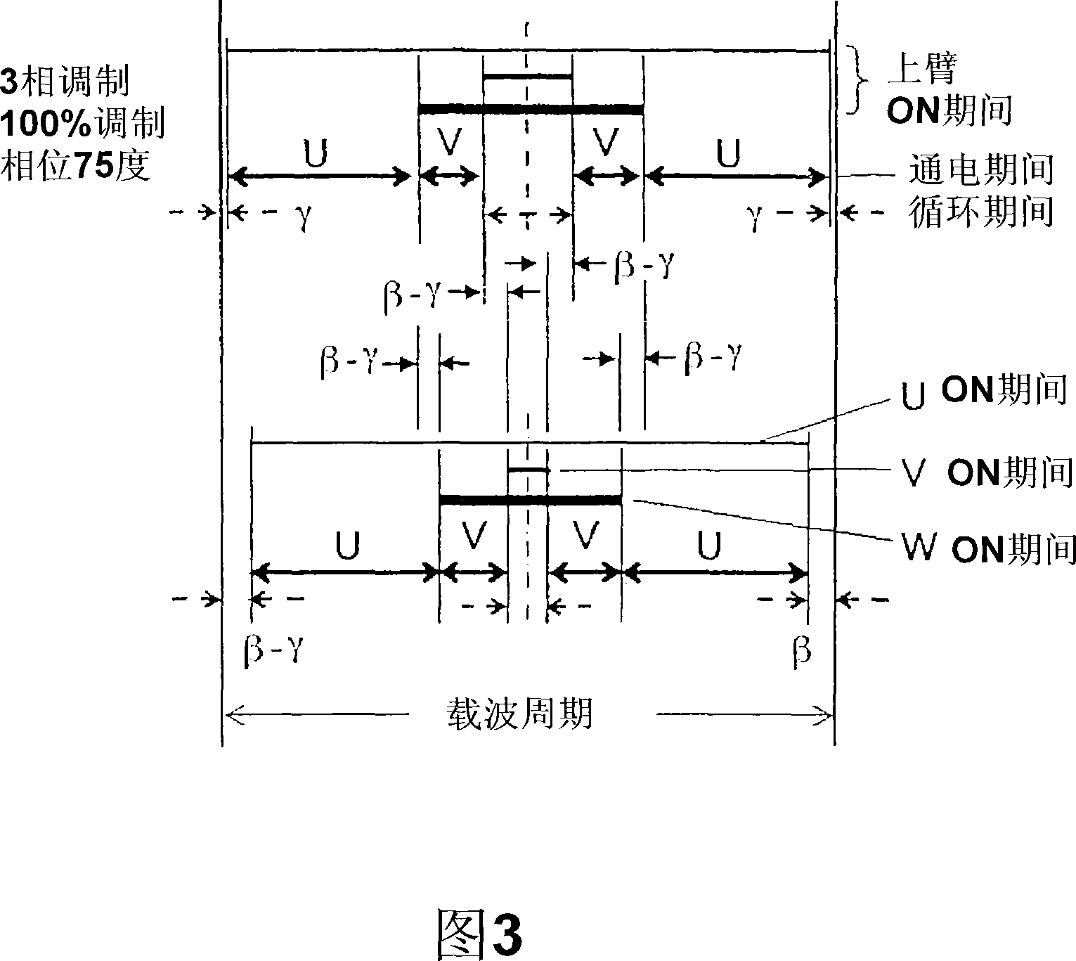
[0110] Similarly, in Fig. 7, when the phase is 75 degrees, the lower side shows that 2(τ-γ) is cut from each ON period of U, V, and W of the upper arm, so that the length (2τ) of the upper cycle period and the length of the lower cycle period The length of (2τ=τ+τ) is the same.
[0111] Therefore, in the preceding and following carriers, the intervals between the energization periods are equal, thereby improving the effect of shortening the car...
Embodiment approach 3
[0115] In FIG. 10 , the inverter device 23 is attached closely to the right side of the electric compressor 40 . The compression mechanism part 28, the motor 11, etc. are provided in the metal frame 32. As shown in FIG.
[0116] The refrigerant is sucked in from the suction port 33 , and the motor 11 drives the compression mechanism unit 28 (scroll in this example), thereby compressing the refrigerant. The compressed refrigerant cools the motor 11 when passing through the motor 11 and is discharged from the discharge port 34 .
[0117] The cassette 30 is used in such a manner that the inverter device 23 is installed in the electric compressor 40 . Inverter circuit unit 10 , which is a heat source, is cooled by the low-pressure refrigerant passing through low-pressure pipe 38 . The inverter device 23 is arranged below the suction pipe 38 so that no dew condensation occurs during this cooling, and the ambient temperature of the inverter circuit unit 10 is also lowered to reduc...
PUM
 Abstract
Description
Claims
Application Information