Multi-pulse ignition circuit for a gas discharge lamp

A technology of gas discharge lamp and ignition circuit, which is applied in the field of ignition circuit and can solve problems such as long time

Inactive Publication Date: 2007-06-27
KONINKLIJKE PHILIPS ELECTRONICS NV
View PDF1 Cites 0 Cited by
  • Summary
  • Abstract
  • Description
  • Claims
  • Application Information

AI Technical Summary

Problems solved by technology

[0005] The downside is that the above ignition circuit is only good for generating pulses with a repetition rate of about 2-3KHz
Therefore, it may take a considerable amount of time before gas breakdown occurs

Method used


Image

  • Multi-pulse ignition circuit for a gas discharge lamp
  • Multi-pulse ignition circuit for a gas discharge lamp

Examples


Embodiment Construction

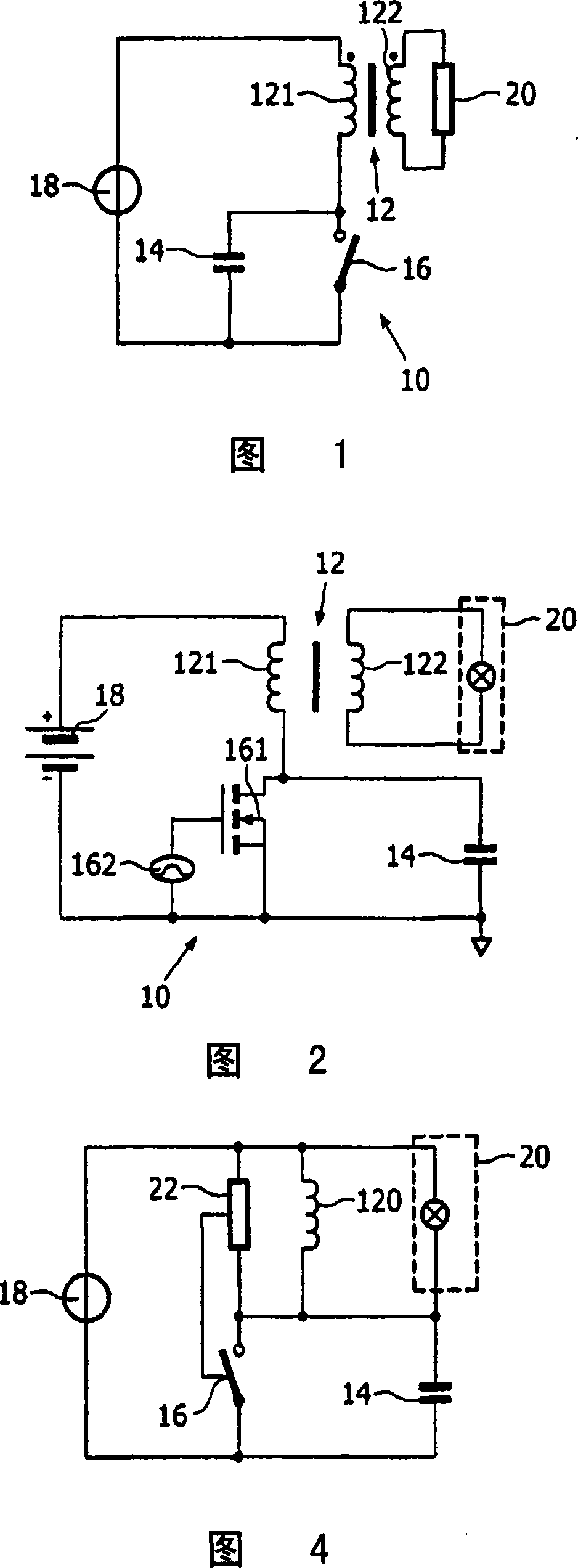
[0026] FIG. 1 shows an ignition circuit 10 comprising a primary winding 121 of a transformer 12 , capacitor 14 and switch 16 . The ignition circuit 10 is coupled to a voltage supply 18 . The secondary winding of the transformer is coupled to a gas discharge lamp circuit 20 . The gas discharge lamp circuit 20 includes a gas discharge lamp and possibly one or more other components.

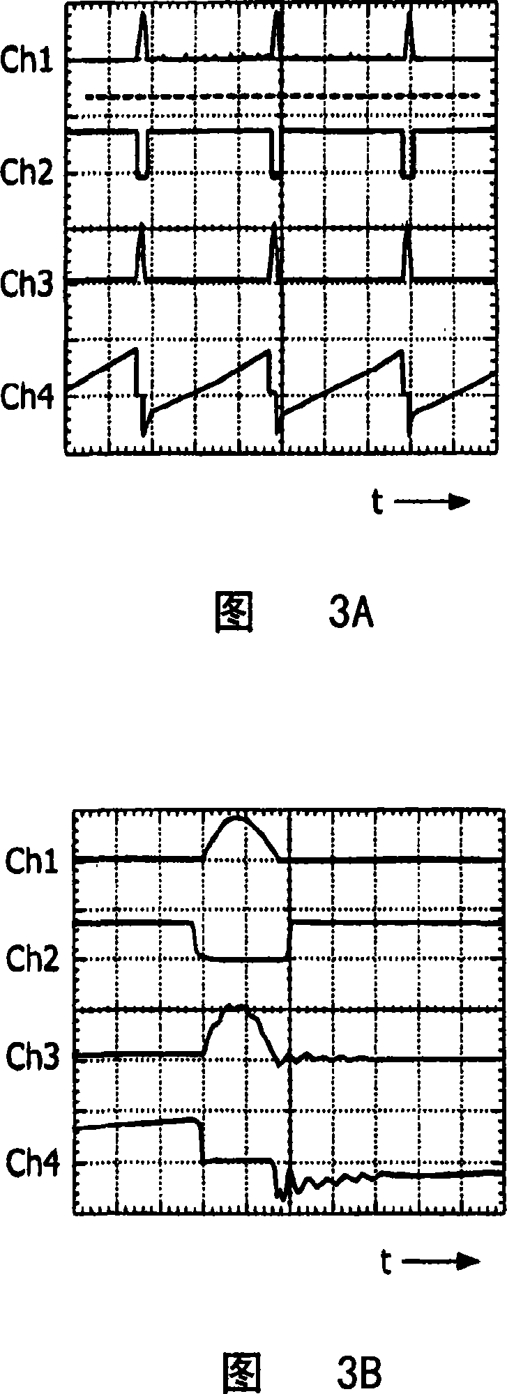
[0027] In the exemplary embodiment shown in FIG. 2 , the switch is specifically a transistor 161 and a switch driving circuit 162 . The transistor 161 is a MOSFET transistor with a body diode. From the following description of the operation of the ignition circuit 10, it will be apparent to those of ordinary skill in the art that any circuit or component suitable for switching current at high frequencies may incorporate the switch. Next, the operation of the ignition circuit according to the present invention will be explained with reference to FIG. 2, FIGS. 3A and 3B.

[0028] In FIGS. 3A and 3...


PUM


Abstract

An ignition circuit for igniting a gas discharge lamp generates a high voltage gas breakdown pulse by building up a current through a primary winding of a transformer. After a predetermined period and thus when a predetermined current flows through the primary winding, a capacitance is switched in series with said primary winding, thereby generating said high voltage gas breakdown pulse in a secondary winding of said transformer. After generating the high voltage pulse, the capacitance is short-circuited in order to preserve energy in the primary winding. The preserved energy is employed to build up energy again for a next high voltage pulse in a short time. At a high repetition rate and high voltage of the generated pulses, the ignition circuit according to the present invention is also suitable for driving the gas discharge lamp during a take-over period following the gas breakdown of the lamp for heating the lamp electrodes.

Description

technical field [0001] The present invention relates to an ignition circuit for a gas discharge lamp, and in particular to a multi-pulse ignition circuit. Background technique [0002] A high ignition voltage is required to start a gas discharge lamp. This high voltage is required to produce gas breakdown between the two electrodes of the lamp. Thereafter, during a take-over, a high voltage is required to heat the electrodes. When the electrodes are heated, a lower operating voltage is required to maintain lamp operation. [0003] The voltage used to produce gas breakdown can be a high voltage pulse. However, the lamp may not start on the first pulse. Therefore, a series of pulses may be required to start the lamp. Furthermore, multi-pulse ignition circuits are known in the prior art. [0004] A multi-pulse ignition circuit is disclosed in US6008591. The ignition circuit consists of a transformer whose secondary winding is connected to the lamp and whose primary windi...

Claims


Application Information

Patent Timeline
Patent Type & Authority Applications(China)
IPC IPC(8): H05B41/282H05B41/28
CPCH05B41/2881H05B41/2821Y02B20/22Y02B20/204H05B41/2806Y02B20/00
Inventor F·斯勒杰斯C·D·C·胡伊杰T·奥斯特巴恩J·A·A·图南
Owner KONINKLIJKE PHILIPS ELECTRONICS NV
Why Eureka
Try Eureka