Lighting device and projector

A technology of lighting device and optical part, applied in projection device, image reproducer using projection device, instrument, etc., can solve problems such as bad influence of viewing image

Inactive Publication Date: 2007-07-04
SEIKO EPSON CORP
View PDF3 Cites 6 Cited by
  • Summary
  • Abstract
  • Description
  • Claims
  • Application Information

AI Technical Summary

Problems solved by technology

If speckles occur in the laser beam that has been magnified and shaped for image display, it will give the viewer a flickering feeling, which will have a bad effect on viewing the image

Method used


Image

  • Lighting device and projector
  • Lighting device and projector
  • Lighting device and projector

Examples


Embodiment 1

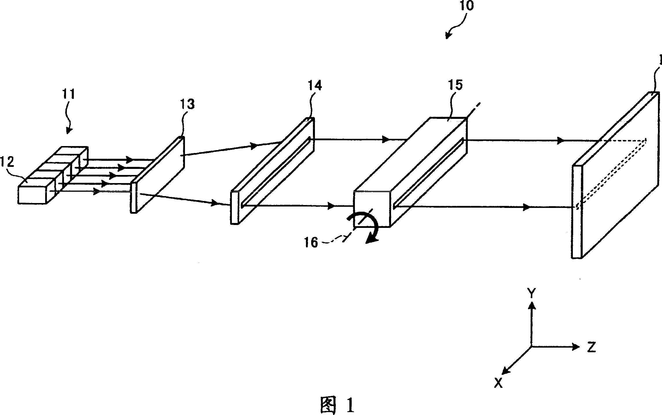
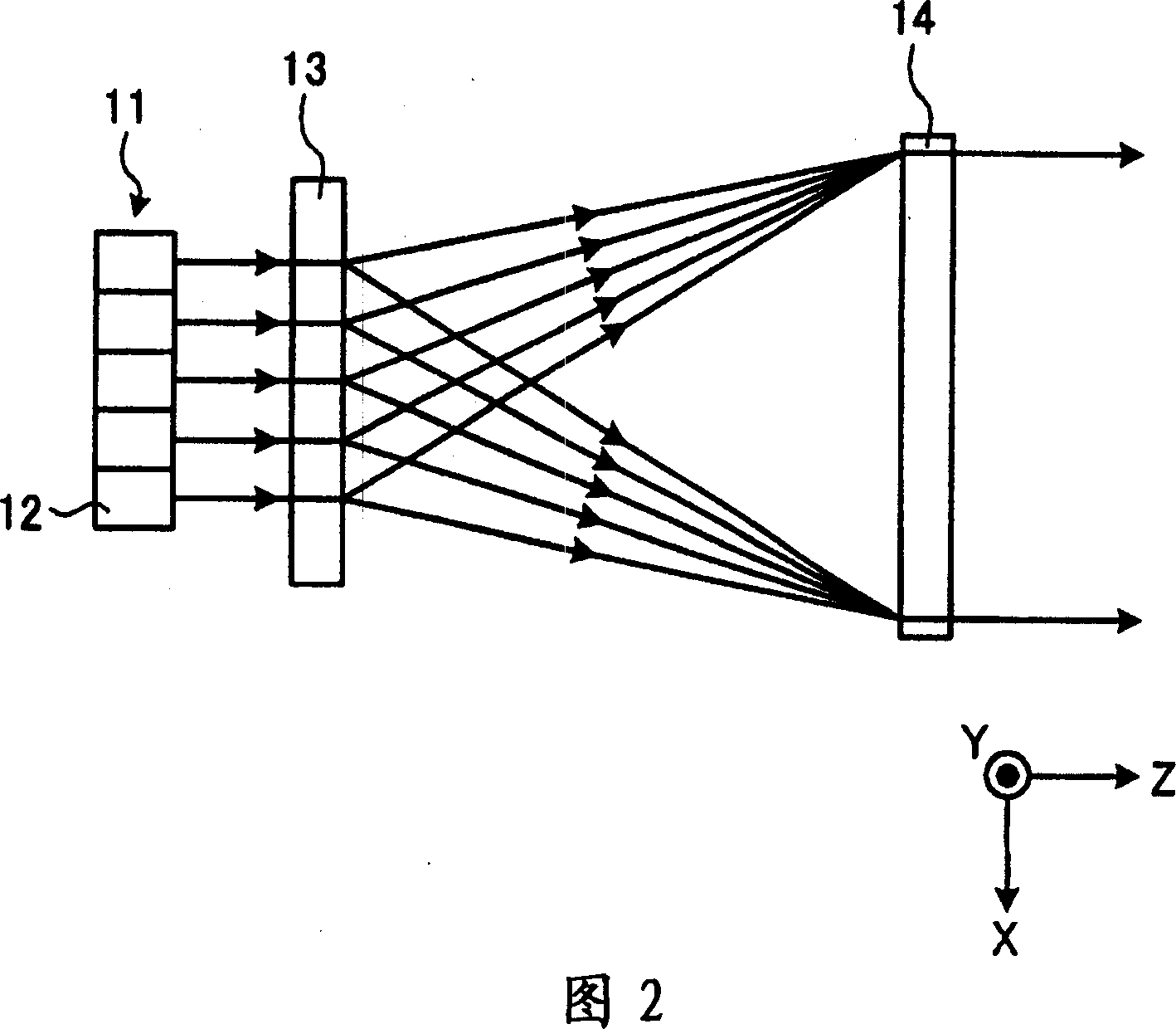
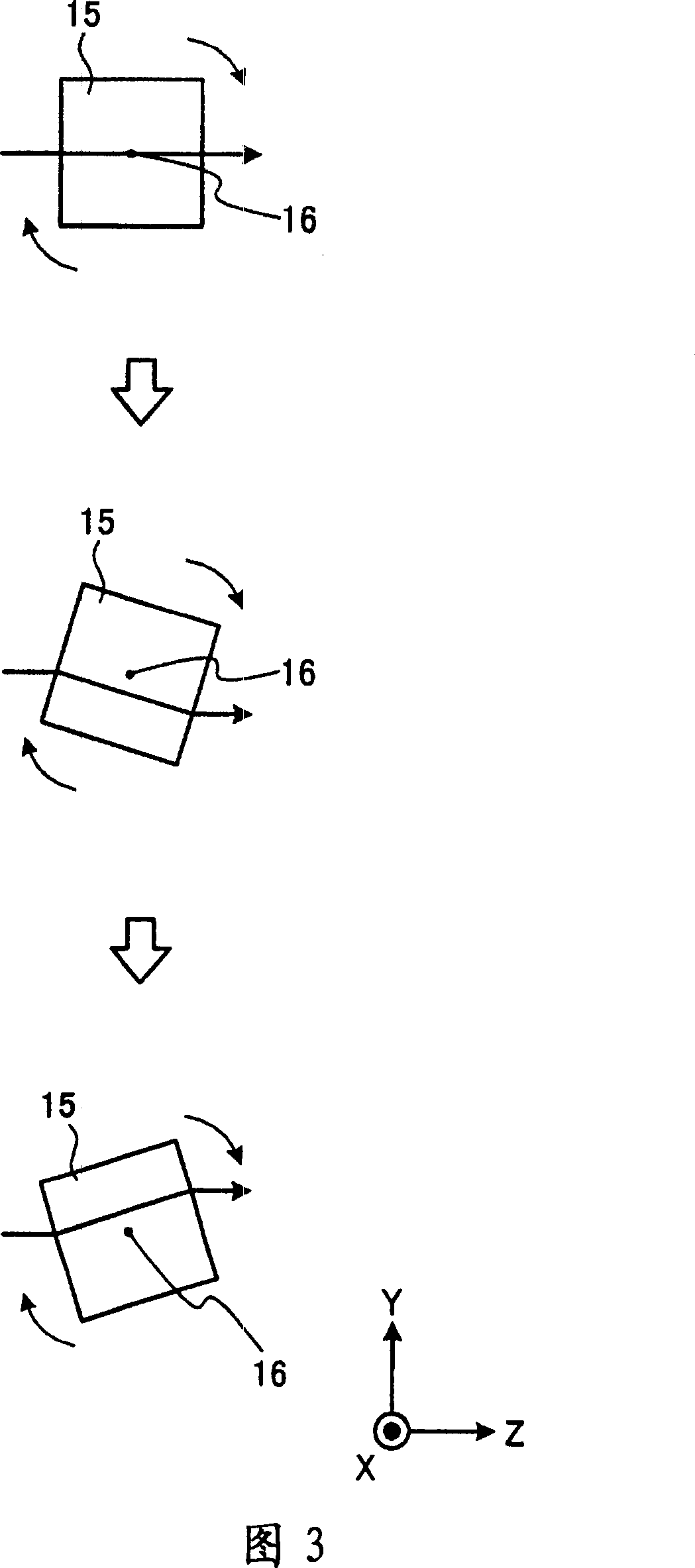
[0038]FIG. 1 shows a schematic configuration of an illumination device 10 in Embodiment 1 of the present invention. Five semiconductor lasers 12 of an end surface emission type are provided in the light source unit 11 . Each semiconductor laser 12 supplies laser light of the same color as a beam of light. The so-called same color refers to having the same or similar wavelength ranges. Five semiconductor lasers 12 are aligned in the X direction which is the first direction. The light source unit 11 provides five laser beams of the same color. Furthermore, the light source unit 11 may employ a wavelength conversion element for converting the wavelength of laser light from the semiconductor laser 12 , for example, a second-harmonic generation (SHG) element. In addition, as the light source unit 11, a surface-emitting semiconductor laser in which five light emitting units are arranged in parallel may be used. Furthermore, instead of the semiconductor laser, a semiconductor las...

Embodiment 2

[0059] FIG. 9 shows a schematic configuration of a projector 100 in Embodiment 2 of the present invention. The projector 100 is a so-called front projection type projector that supplies light to a screen 96 provided on the viewer's side, and enjoys an image by viewing the light reflected by the screen 96 . The projector 100 is characterized by including lighting devices 10R, 10G, and 10B for each color light having the same configuration as the lighting device 10 in the first embodiment described above.

[0060] The R light source unit 11R provided in the red light (hereinafter referred to as "R" light) illumination device 10R supplies R light. The G-light light source unit 11G provided in the green light (hereinafter referred to as "G" light.) illumination device 10G supplies the G-light. The B-light light source unit 11B provided in the blue light (hereinafter referred to as "B" light.) illumination device 10B supplies the B-light. The projector 100 has a plurality of ligh...


PUM


Abstract

A lighting device includes: a light source which supplies a beam; a shaping optical portion which shapes the beam into a linear luminous flux approximately parallel to a first direction; and a scanner which causes the linear luminous flux to scan in a second direction approximately perpendicular to the first direction.

Description

technical field [0001] The present invention relates to an illuminating device and a projector, in particular to the technology of an illuminating device using laser light. Background technique [0002] In recent years, along with the increase in output of semiconductor lasers and the development of blue semiconductor lasers, projectors, displays, and the like that display images using laser light have been proposed. Because the laser has a single wavelength, it has high color purity, high coherence, and easy shaping. Compared with the ultra-high pressure mercury lamps used in the past, the laser light source has advantages such as small size and instantaneous lighting. Therefore, it is expected that high-quality images can be displayed with a compact structure by using laser light. In the case of replacing the conventionally used ultra-high pressure mercury lamp with a laser light source, in order to obtain sufficient brightness, it is considered to use an array laser in ...

Claims


Application Information

Patent Timeline
Patent Type & Authority Applications(China)
IPC IPC(8): G03B21/14G02B27/00G02F1/01H04N5/74H04N9/31
CPCG02B27/0944G02B19/0057G02B19/0009G02B19/0028G02B26/108G02B27/0922G02B26/105H04N9/3129
Inventor 永田光夫
Owner SEIKO EPSON CORP
Why Eureka
Try Eureka