Method for creating three-dimensional finite element mesh

A finite element and mesh technology, applied in the field of generating 3D finite element meshes, can solve the problems of complex hexahedral mesh process, 3D mesh modeling taking a lot of time, and difficulty in the field of engineering design.

Active Publication Date: 2007-07-04
靖江德方科技服务有限公司
View PDF0 Cites 24 Cited by
  • Summary
  • Abstract
  • Description
  • Claims
  • Application Information

AI Technical Summary

Problems solved by technology

From a literal point of view, it can be realized that the process of manually dividing the hexahedral mesh is very complicated. Usually, it will take a long time for a shape with a moderate difficulty to perform hexahedral meshing, usually several months.
Because 3D grid modeling takes a lot of time, it creates a bottleneck for subsequent analysis and design, which is a basic problem in the field of engineering design.

Method used


Image

  • Method for creating three-dimensional finite element mesh
  • Method for creating three-dimensional finite element mesh
  • Method for creating three-dimensional finite element mesh

Examples


Embodiment Construction

[0033] The present invention will be further described below in conjunction with the drawings and specific embodiments.

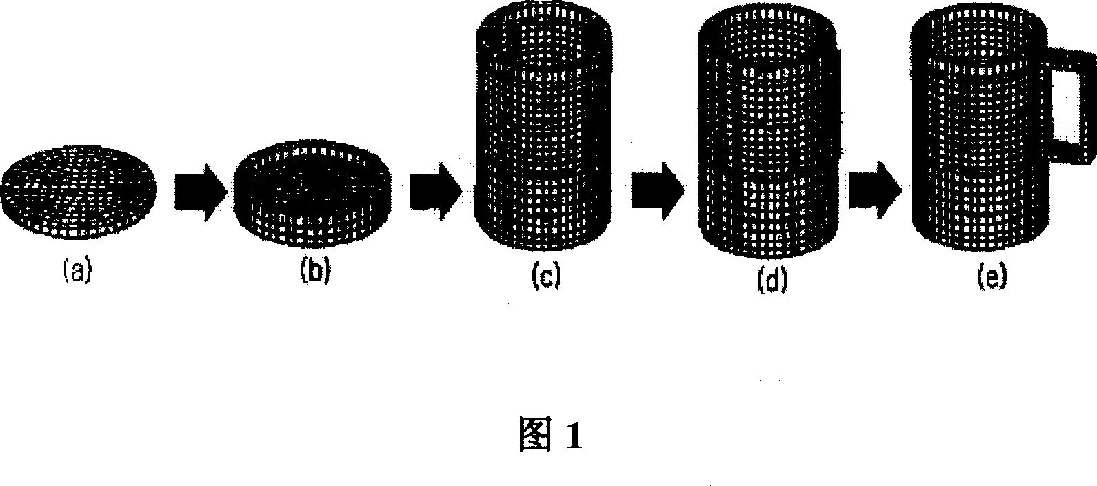
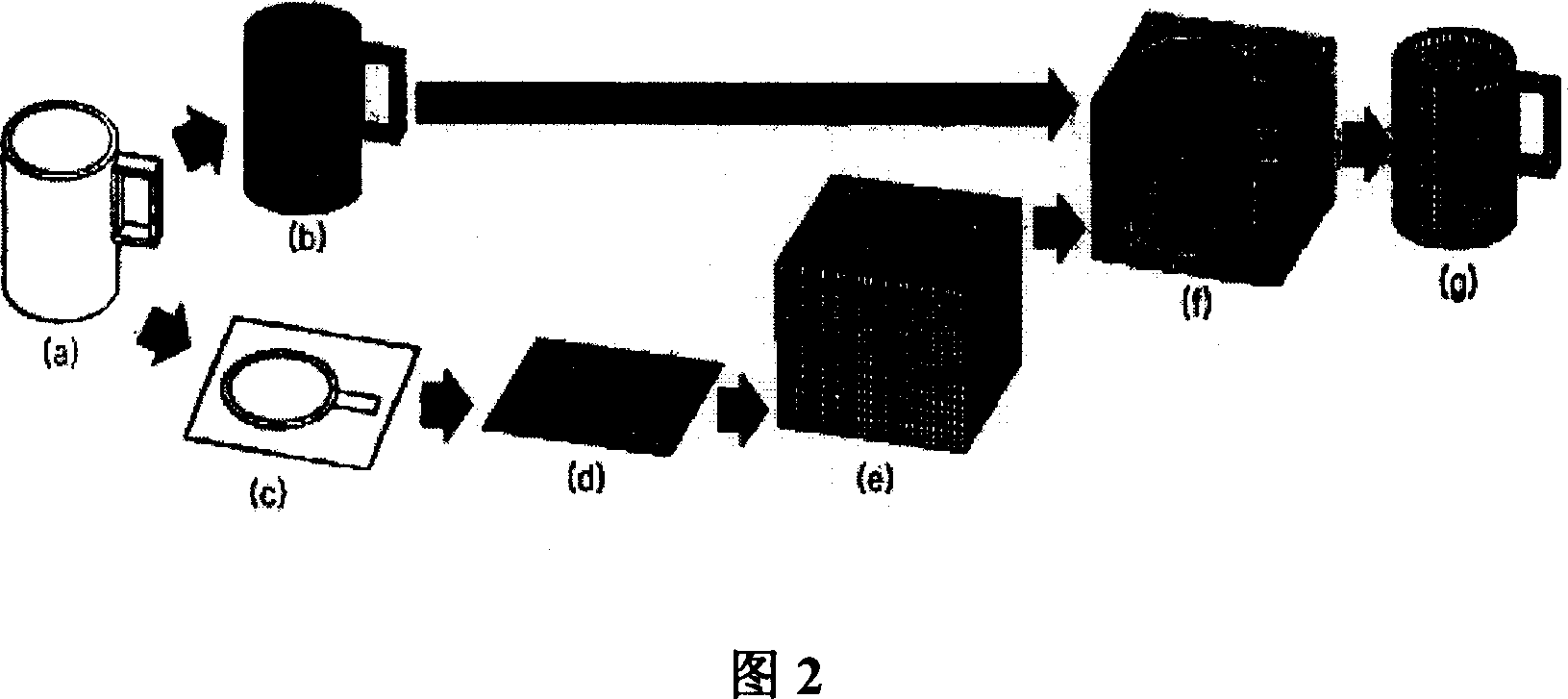
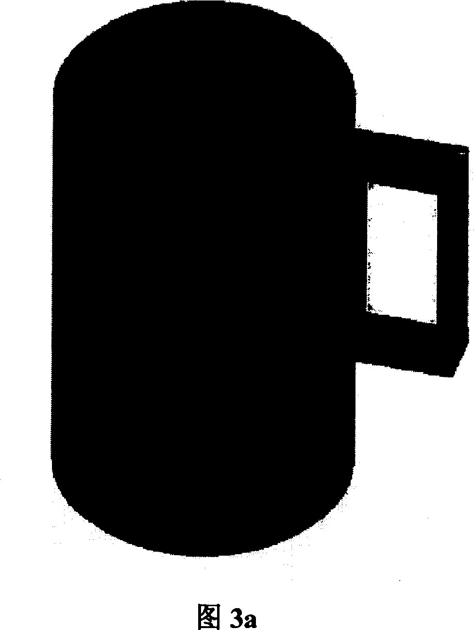
[0034] As shown in Figure 2 and Figure 3a to Figure 3e, a three-dimensional finite element mesh generation process of a cup is taken as an example. For the entity of a cup, as shown in Figure 2a, a three-dimensional model of it needs to be established first, which can be established by CAD modeling software. The second step is to create a grid on the surface of the cup. Use the CAD model of the cup to build the surface mesh, as shown in Figure 2b and Figure 3a. The generation method of the surface mesh is the traditional meshing method, and its basic principle is to obtain the corresponding surface mesh through node connection. For engineering analysts, it can be implemented very easily. The third step is to draw the projection contour line of the cup CAD model, as shown in Figure 2c and Figure 3b, and project the cup vertically onto the horizontal plane where ...


PUM


Abstract

The invention belongs to fields of computer image processing; a method of generating three-dimensional finite element grid is disclosed that includes steps as following: 101. Two-dimension surface grid is divided on surface of the three-dimensional model of object noumenon; 102. The noumenon basic grid which encompasses the three-dimensional model is generated by the noumenon basic grid built by projection borderline; 103. The Two-dimension surface grid is inserted into the back of the noumenon basic grid, eliminating the noumenon grid which is out of the noumenon surface grid; the noumenon three-dimensional grid needed is obtained. Because said technical project is adopted, the Two-dimension surface grid and the noumenon basic grid are obtained easily, for adopting the penetration algorithm, the time of generating final noumenon grid is decreased than traditional approach, quantity of work in several months can be accomplished within several days even several hours. At the same time, because the three-dimensional noumenon grid generated is hexahedron grid, the quantity of grid id higher, the calculation error can be improved greatly.

Description

[Technical Field] [0001] The present invention relates to computer image processing technology, in particular to a method for generating three-dimensional finite element meshes. [Background technique] [0002] In the production of various manufacturing industries, such as the design and manufacturing process of automobile products, it is necessary to carry out force and deformation analysis, fluid fluidity analysis, or electromagnetic field analysis of structural components to achieve the purpose of saving design costs and shortening the product launch cycle. . A three-dimensional model of the product is usually established in a computer as the basis for analysis. The current Pro-Engineer, CATIA, and Patran can be used as 3D modeling tools, and CAD (Computer Aided Drafting) is usually used as a basic finite element analysis tool. [0003] As the initial process of the 3D finite element method, a structure or mechanical part to be analyzed is first divided into small units of a ce...

Claims


Application Information

Patent Timeline
Patent Type & Authority Applications(China)
IPC IPC(8): G06F17/50
Inventor 张岩谢卿
Owner 靖江德方科技服务有限公司
Why Eureka
Try Eureka