
Method for manufacturing semiconductor device

A semiconductor and plasma technology, which is applied in semiconductor/solid-state device manufacturing, photolithographic process of patterned surface, optics, etc., can solve the problems of total productivity decline and overall process complexity

Inactive Publication Date: 2007-07-04
SK HYNIX INC
View PDF0 Cites 3 Cited by
  • Summary
  • Abstract
  • Description
  • Claims
  • Application Information

AI Technical Summary

Problems solved by technology

[0008] However, in the conventional method described above, the photoresist film, anti-reflection film, and hard mask layer must be coated and etched twice, respectively, in order to form a fine pattern
Therefore, the overall process becomes complicated, resulting in a decrease in overall productivity

Method used


Image

  • Method for manufacturing semiconductor device
  • Method for manufacturing semiconductor device
  • Method for manufacturing semiconductor device

Examples


Embodiment Construction

[0045] Disclosed herein is a method of manufacturing a semiconductor device, which includes sequentially forming an underlayer, a hard mask layer, an antireflection film, and a first photoresist film containing Si on a semiconductor substrate. The method also includes exposing and developing the first photoresist film using a first exposure mask to form a first photoresist pattern, and performing O on the first photoresist pattern. 2 plasma treatment. This method is also included in the O 2 forming a second photoresist film on the plasma-treated first photoresist pattern, and exposing and developing regions intersecting with the first photoresist pattern using a second exposure mask to form A second photoresist pattern. The method also includes etching the anti-reflection film using the first and second photoresist patterns as a mask, thereby forming an anti-reflection pattern, and etching the hard mask layer using the anti-reflection pattern as a mask to form a hard mask p...


PUM


Abstract

Disclosed herein is a method for manufacturing a semiconductor device that includes performing an O2 plasma treatment step after forming a Si-containing photoresist film.

Description

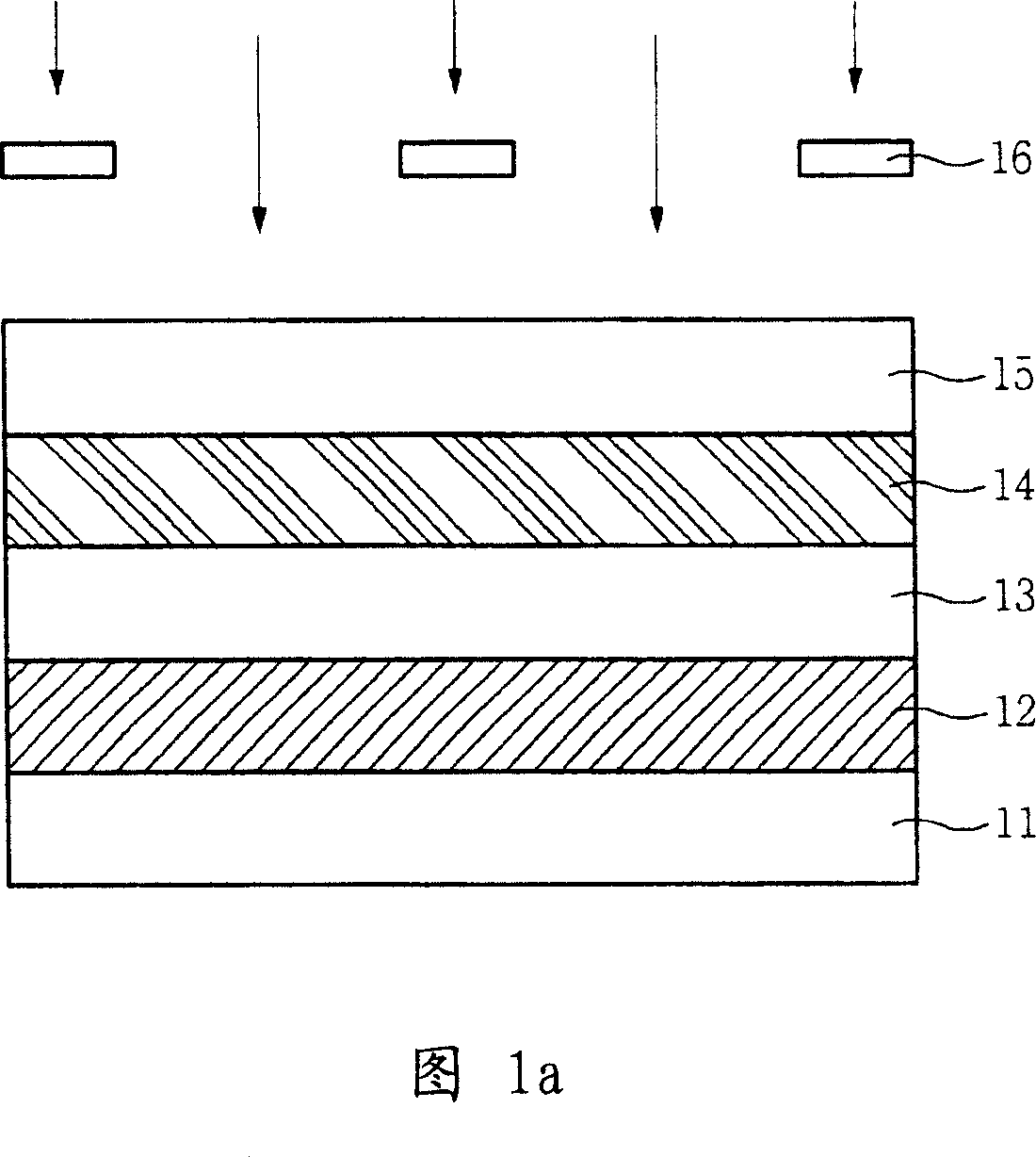
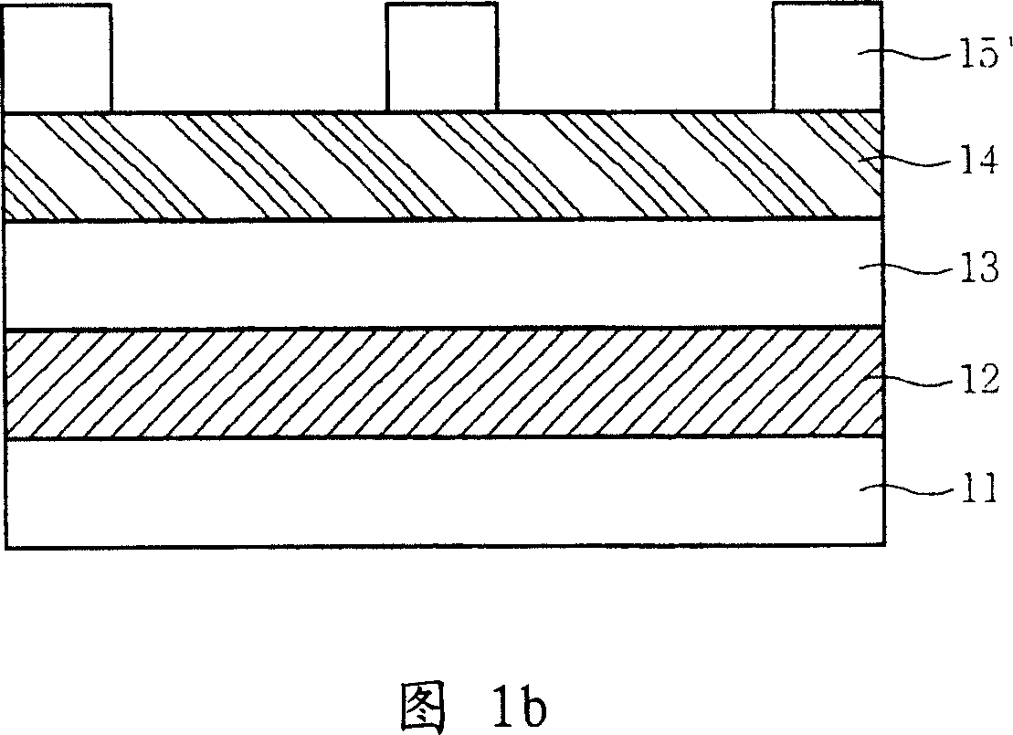
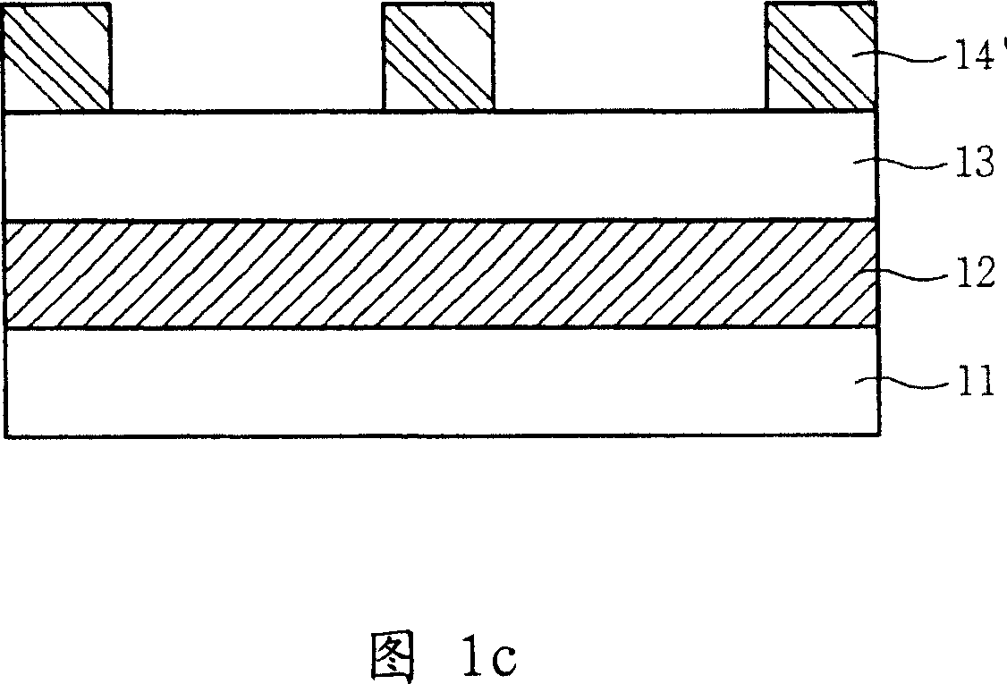
technical field [0001] In general terms, the present invention relates to a method of manufacturing a semiconductor device. More particularly, the present invention relates to a patterning method that can overcome resolution limitations of lithography for fabricating semiconductor devices. Background technique [0002] Recently, a double exposure method has been performed to form fine patterns of semiconductor devices in order to overcome resolution limitations of exposure equipment. This general method is described below. [0003] Referring to FIGS. 1 a and 1 b , a bottom layer 12 , a first hard mask layer 13 , a first anti-reflection film 14 , and a first photoresist film 15 are sequentially formed on a semiconductor substrate 11 . A first region of the entire surface is exposed using a first exposure mask 16, and the exposed photoresist film 15 is developed to form a first photoresist pattern 15'. The hard mask layer 13 is usually a double layer composed of an amorphou...

Claims


Application Information

Patent Timeline
Patent Type & Authority Applications(China)
IPC IPC(8): H01L21/00H01L21/027G03F7/00G03F7/40
CPCH01L21/0276H01L21/0337H01L21/0338H01L21/31144
Inventor 李晟求郑载昌
Owner SK HYNIX INC
Learn More