Device and method for measuring quality factor of homology sampling

A quality factor and measurement device technology, applied in transmission monitoring/testing/fault measurement systems, electromagnetic wave transmission systems, electrical components, etc., can solve the problem of high complexity and equipment cost, and the difficulty of optical signal phase coherence in broadband optical frequency-locked circuits And other issues

Inactive Publication Date: 2007-07-04
IND TECH RES INST
View PDF1 Cites 0 Cited by
  • Summary
  • Abstract
  • Description
  • Claims
  • Application Information

AI Technical Summary

Problems solved by technology

[0017] The coherence detection module of the prior art, for example, US Patent No. US2005 / 0185255 A1 published on August 25, 2005, its quality factor monitoring technology consists of a wavelength tunable optical pulse laser (wavelength tunable) with the same wavelength as the measured optical signal Optical pulse laser) and the optical signal under test are coupled into the optical receiver together, and the optical pulse (optical pulse) output by this wavelength-tunable optical pulse laser replaces the above-mentioned continuous light to amplify and sample the signal, and the part with the same wavelength is obtained by A wide-band optical frequency-locked loop is implemented. However, although this architecture can achieve quality factor monitoring, the complexity and equipment cost are quite high, and when operating at high frequencies, it is not easy for the wide-band optical frequency-locked loop to achieve the function of optical signal phase coherence.

Method used


Image

  • Device and method for measuring quality factor of homology sampling
  • Device and method for measuring quality factor of homology sampling
  • Device and method for measuring quality factor of homology sampling

Examples


Embodiment Construction

[0048] The detailed features and advantages of the present invention are described in detail below in the embodiments, the content of which is sufficient to enable any person familiar with the related art to understand the technical content of the present invention and implement it accordingly, and according to the content disclosed in this specification, the patent scope of the application and the drawings , anyone skilled in the related art can easily understand the related objects and advantages of the present invention.

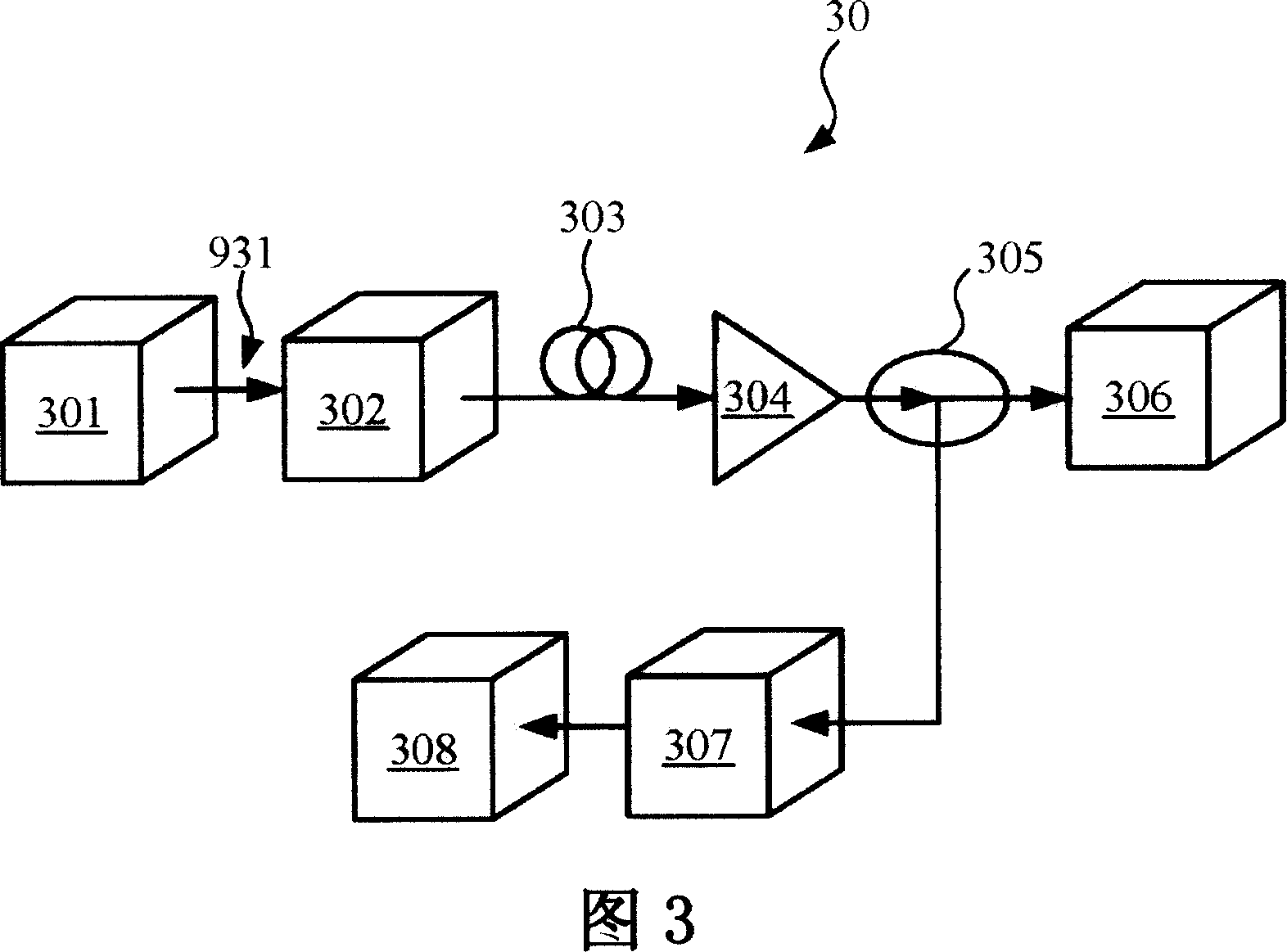
[0049] As shown in Figure 3, the optical signal 931 is divided into two parts by the optical splitter 305, and a part of the optical signal to be measured enters the quality factor measurement module 307 to receive the optical signal quality detection. The present invention proposes a comparison for the quality factor measurement module 307. Good example. The invention uses a wavelength converter and a laser diode to convert the wavelength of the optical ...


PUM


Abstract

A same-type sampling quality factor measuring device and method is used for real-time monitoring optical signal quality in optical network, and the quality is assessed by the quality factor, and the device using laser diode with wavelength converter to obtain the same-type wavelength and amplify the optical signal, and using laser diode with optical switch to obtain sampling optical pulse, and therefore, after access to photoelectric converter, the optical signal is amplified and coupled with the optical pulse to rebuild the basic frequency signal of the optical signal, thereby to detect the quality factor, and monitor optical signal quality.

Description

technical field [0001] The present invention relates to a device and method for measuring the quality of an optical signal, which is used in a monitoring system of an optical network to detect the quality factor (Q-factor) of the optical signal and evaluate the bit error rate (bit) of the optical signal. error rate, BER). Background technique [0002] Driven by the trend of high-speed optical network / all-optical network, the transmission rate has increased to megabits per second and the transmission distance has become farther and farther. When optical signals are transmitted in channels, there are quite a few factors that will affect the quality of data transmission. Therefore, it is necessary to establish a good optical signal quality monitoring system, so as to effectively manage the optical network and improve performance. However, in addition to the gradual reduction of traditional electricity nodes, the electricity network performance monitors with traditional electri...

Claims


Application Information

Patent Timeline
IPC IPC(8): H04B10/08H04J14/02H04B10/07
Inventor 徐达儒李三良
Owner IND TECH RES INST
Why Eureka
Try Eureka