Sound generator module, sound generating structure and electronic device utilizing the same
A sound and piezoelectric vibration technology, applied to electrical components, piezoelectric/electrostrictive transducers, sensors, etc., to achieve the effects of ensuring sound pressure characteristics, easy manufacturing, and thinning
- Summary
- Abstract
- Description
- Claims
- Application Information
AI Technical Summary
Problems solved by technology
Method used
Image

Examples
Embodiment 1
[0105] (basic structure)
[0106] First, Embodiment 1 of the present invention will be described with reference to FIGS. 1 to 6 .
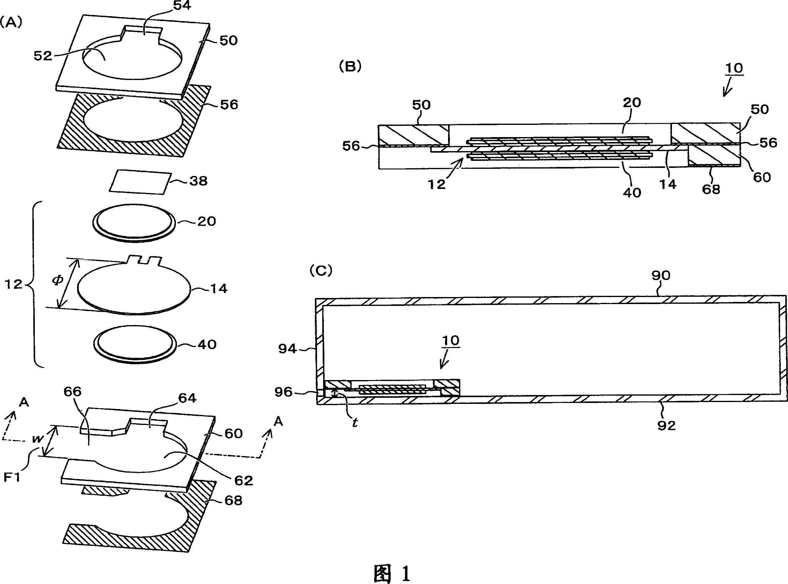
[0107] Next, referring to FIG. 1, the basic structure of this embodiment will be described. Fig. 1 (A) is the disassembled perspective view of the sounding body module of the present embodiment, and Fig. 1 (B) is under the state that above-mentioned sounding body module has been assembled, above-mentioned Fig. 1 (A) is cut along the A-A line, to arrow indicated 1 (C) is a cross-sectional view showing an installation example of the above-mentioned sounding body module. As shown in FIG. 1(C) above, the sounding body module 10 of the present embodiment is installed inside a casing 90 of an electronic device.
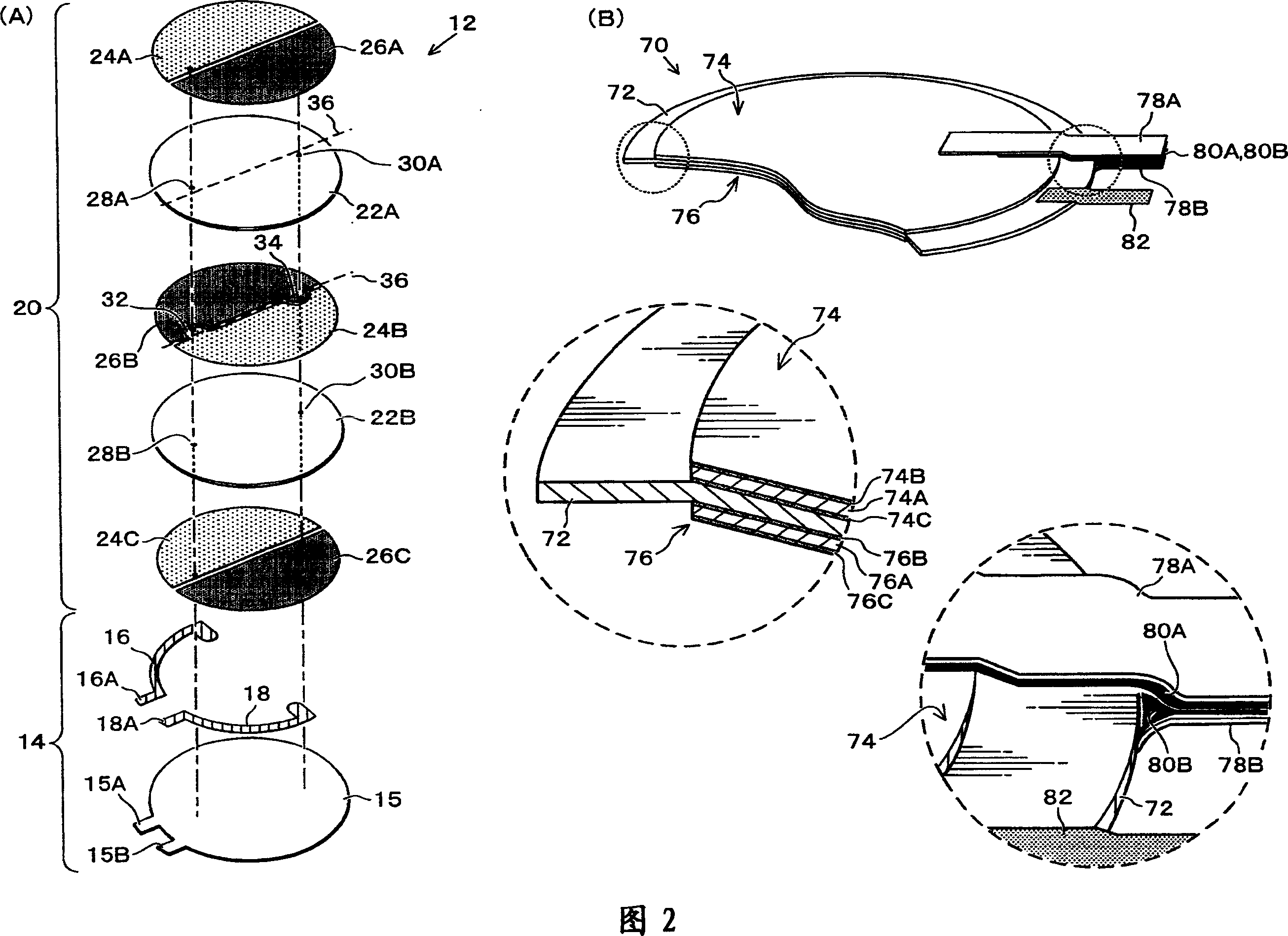
[0108] As shown in FIGS. 1(A) and 1(B), the sounding body module 10 has a structure in which a piezoelectric diaphragm 12 , a sheet-shaped holding member 50 and an acoustic space forming member 60 are laminated. The piezoelectric vibrating p...
Embodiment 2
[0141] Next, Embodiment 2 of the present invention will be described with reference to FIG. 7 . The same reference numerals are used for the same or corresponding components as in the first embodiment described above (the same applies to the following embodiments). Fig. 7 (A) is the disassembled perspective view of the sounding body module of the present embodiment, and Fig. 7 (B) is under the state that above-mentioned sounding body module has been assembled, above-mentioned Fig. 7 (A) is cut along the B-B line, to arrow place A cross-sectional view viewed in the direction shown. The first embodiment described above is an example in which the holding member 50 and the acoustic space forming member 60 are formed of the same material, and is suitable for a case where the frame body 90 is hard and smooth. An example in which the acoustic space forming member 60 is formed of a different material.
[0142]The basic structure of the sounding body module 100 of the present embodim...
Embodiment 3
[0144] Next, Embodiment 3 of the present invention will be described with reference to FIG. 8 . Fig. 8 (A) is the exploded perspective view of the sounding body module of the present embodiment, and Fig. 8 (B) shows an installation example of above-mentioned sounding body module, is equivalent to above-mentioned Fig. 8 (A) is cut along C-C line, to arrow direction A cross-sectional view obtained by looking at it. The above-mentioned Embodiment 1 and Embodiment 2 have a structure in which one sounding body module has one piezoelectric vibrating plate, but this embodiment 3 has a structure in which one sounding body module has two piezoelectric vibrating plates. The sounding body module 120 of the present embodiment is composed of two piezoelectric vibrating plates 12A and 12B, their holding member 122 , and an acoustic space forming member 130 .
[0145] The piezoelectric vibrating plates 12A and 12B have the same structure as the piezoelectric vibrating plate 12 of the first ...
PUM
 Abstract
Description
Claims
Application Information
 - R&D
- Intellectual Property
- Life Sciences
- Materials
- Tech Scout
- Unparalleled Data Quality
- Higher Quality Content
- 60% Fewer Hallucinations
Browse by: Latest US Patents, China's latest patents, Technical Efficacy Thesaurus, Application Domain, Technology Topic, Popular Technical Reports.
© 2025 PatSnap. All rights reserved.Legal|Privacy policy|Modern Slavery Act Transparency Statement|Sitemap|About US| Contact US: help@patsnap.com