Air intake mode of the fuel battery

A fuel cell and single cell technology, applied in the direction of fuel cell additives, etc., can solve the problems of poor battery performance, reduce humidity, etc., achieve the goals of improving water distribution, reducing concentration polarization, and improving stability and life Effect

Inactive Publication Date: 2007-07-11
CHUNLAN GROUP CORP
View PDF0 Cites 2 Cited by
  • Summary
  • Abstract
  • Description
  • Claims
  • Application Information

AI Technical Summary

Problems solved by technology

There are many ways to improve battery performance under high current density and reduce concentration polarization, such as adjusting humidity, improving electrode structure and air intake mode, but reducing humidity will lead to poor battery performance at lower current density

Method used


Image

  • Air intake mode of the fuel battery
  • Air intake mode of the fuel battery
  • Air intake mode of the fuel battery

Examples


Embodiment Construction

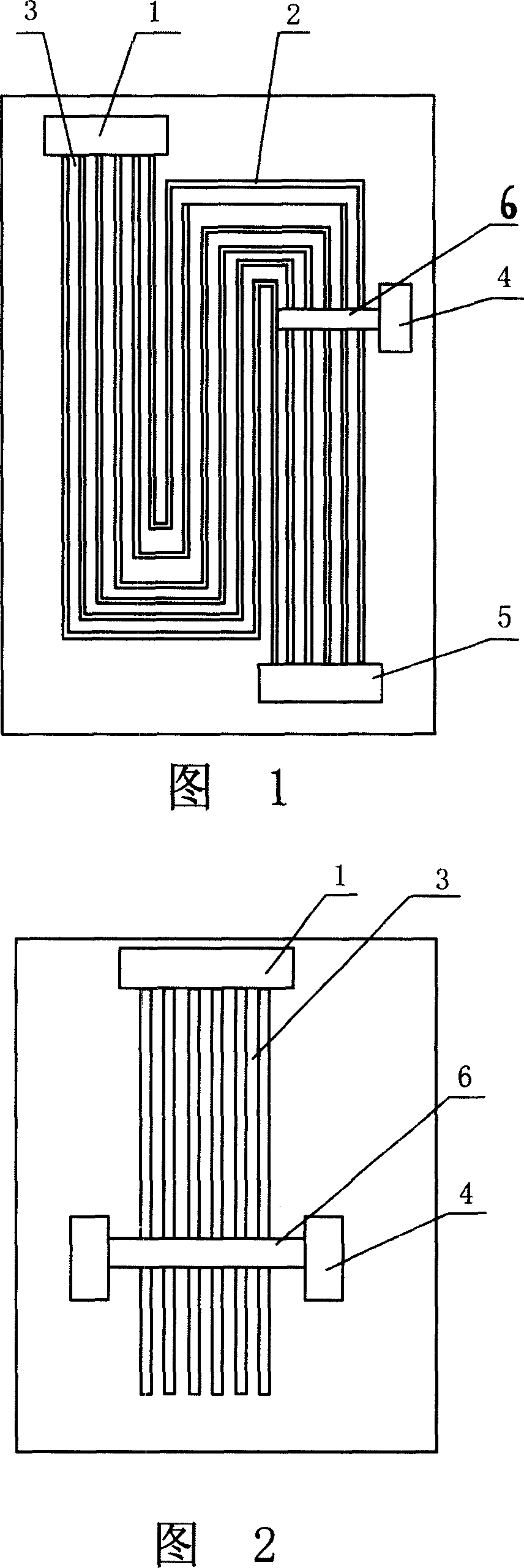
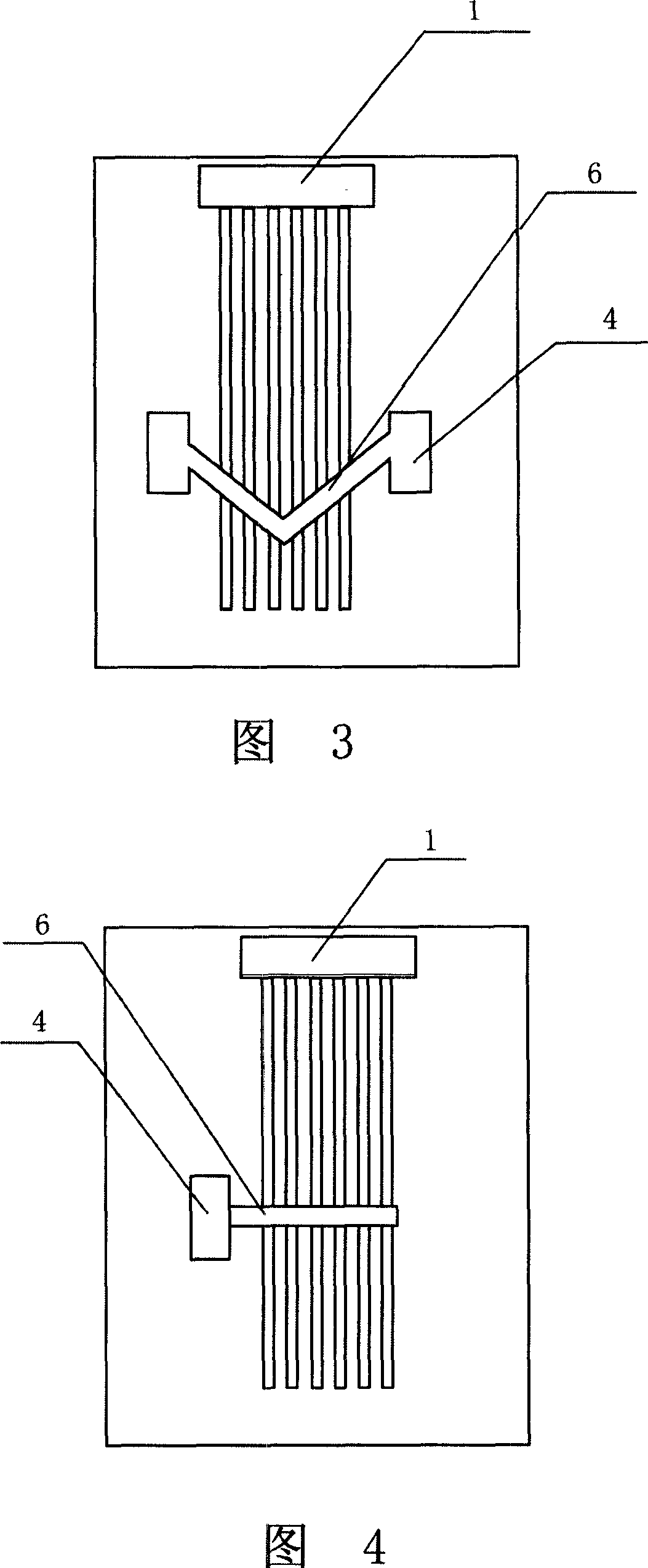
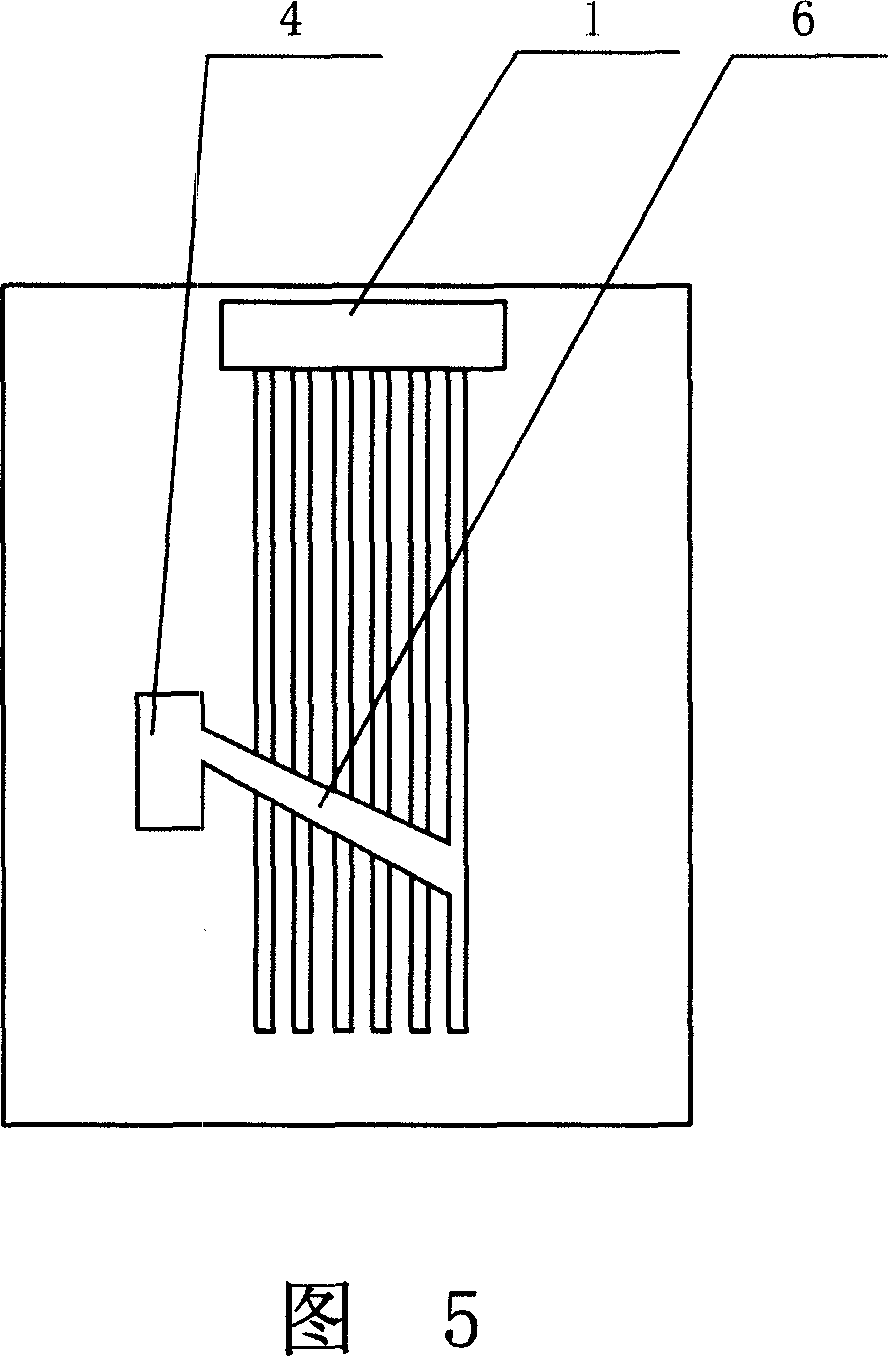
[0021] Referring to Figure 1, a fuel cell is composed of several single cells fixed by end plates on both sides, and each single cell is composed of a cathode flow field plate, an anode flow field plate, a diffusion layer, a catalytic layer and a proton exchange membrane. The flow channel 2 of the flow field plate of the single cell takes in air through the main air inlet 1 and air out through the air outlet 5 . To realize the secondary air intake, the secondary air intake 4 is mainly added on the cathode flow field plate or the anode flow field plate, and the secondary air intake 4 communicates with the flow channel 2 . Adding the secondary air inlet 4 on the flow field plate is not only applicable to the multiple serpentine flow channels in the figure, but also applicable to other flow channels such as straight flow channels and single serpentine flow channels.

[0022] The position of the secondary air inlet 4 is not limited to the position in the figure, generally it shoul...


PUM

PropertyMeasurementUnit
thicknessaaaaaaaaaa

Abstract

This invention discloses one fuel battery gas in method, wherein, the battery comprises multiple single cells, main gas in hole and exit hole, wherein, the single battery field channel exhausts from main gas in hole; the said current field board is set with secondary gas in holes to realize second gas in with pressure less than main gas pressure to improve battery gas distribution status.

Description

technical field [0001] The invention relates to an intake method of a fuel cell. Background technique [0002] Proton exchange membrane fuel cell (PEMFC), as a new type of energy processing method, has the advantages of low operating temperature, no pollution, no corrosion, high specific power, and rapid start-up, and has become one of the hotspots in the field of energy research. The application prospect of fuel cell generator set is very broad. In terms of small and micro, microcomputers and power sources from a few watts to less than 5 kilowatts can be built, such as for single and double vehicles; home phones, electric stoves, and long-life power supplies for mobile communications, notebook computers, and mobile phones; large-scale On the one hand, it can be used for cars with dozens or hundreds of kilowatts, bus trucks, tanks, submarine power plants, independent power grids, mines, and dock power supplies. The universal application in all aspects will drive a huge ind...

Claims


Application Information

Patent Timeline
Patent Type & Authority Applications(China)
IPC IPC(8): H01M8/04
CPCY02E60/50
Inventor 薛昆岳江宁
Owner CHUNLAN GROUP CORP
Why Eureka
Try Eureka