A rotating electrical machine with a transmission and a driving apparatus using the same

A technology of speed change mechanism and rotating electrical machine, applied in electromechanical devices, electric components, synchronous machines, etc., can solve the problems of hard resin material sealing, enlarged motor shape, large surface area of ​​excitation coil, etc., and achieve the effect of small outer diameter

Inactive Publication Date: 2007-07-11
HITACHI IND EQUIP SYST CO LTD +2
View PDF2 Cites 1 Cited by
  • Summary
  • Abstract
  • Description
  • Claims
  • Application Information

AI Technical Summary

Problems solved by technology

[0008] However, in general, if it is desired to arrange a speed change mechanism inside the rotor or stator of these electric motors, a certain amount of space is required because a gear having the number of teeth corresponding to the reduction gear ratio is required.
Therefore, there is a problem that the outer diameter of the motor becomes larger than the smallest motor outer diameter for outputting the necessary torque, and even if a high torque can be achieved by gear reduction, it is not compatible with the system as a whole directly using a low-speed high-torque motor. Compared with the situation, the problem that the miniaturization effect cannot be strengthened
However, when a protective cover is provided, the outer shape of the motor increases due to the protective cover, and when sealed with a resin material, there is a problem that it is difficult to seal with a resin material because the surface area of ​​the field coil is large.

Method used


Image

  • A rotating electrical machine with a transmission and a driving apparatus using the same
  • A rotating electrical machine with a transmission and a driving apparatus using the same
  • A rotating electrical machine with a transmission and a driving apparatus using the same

Examples


no. 1 approach

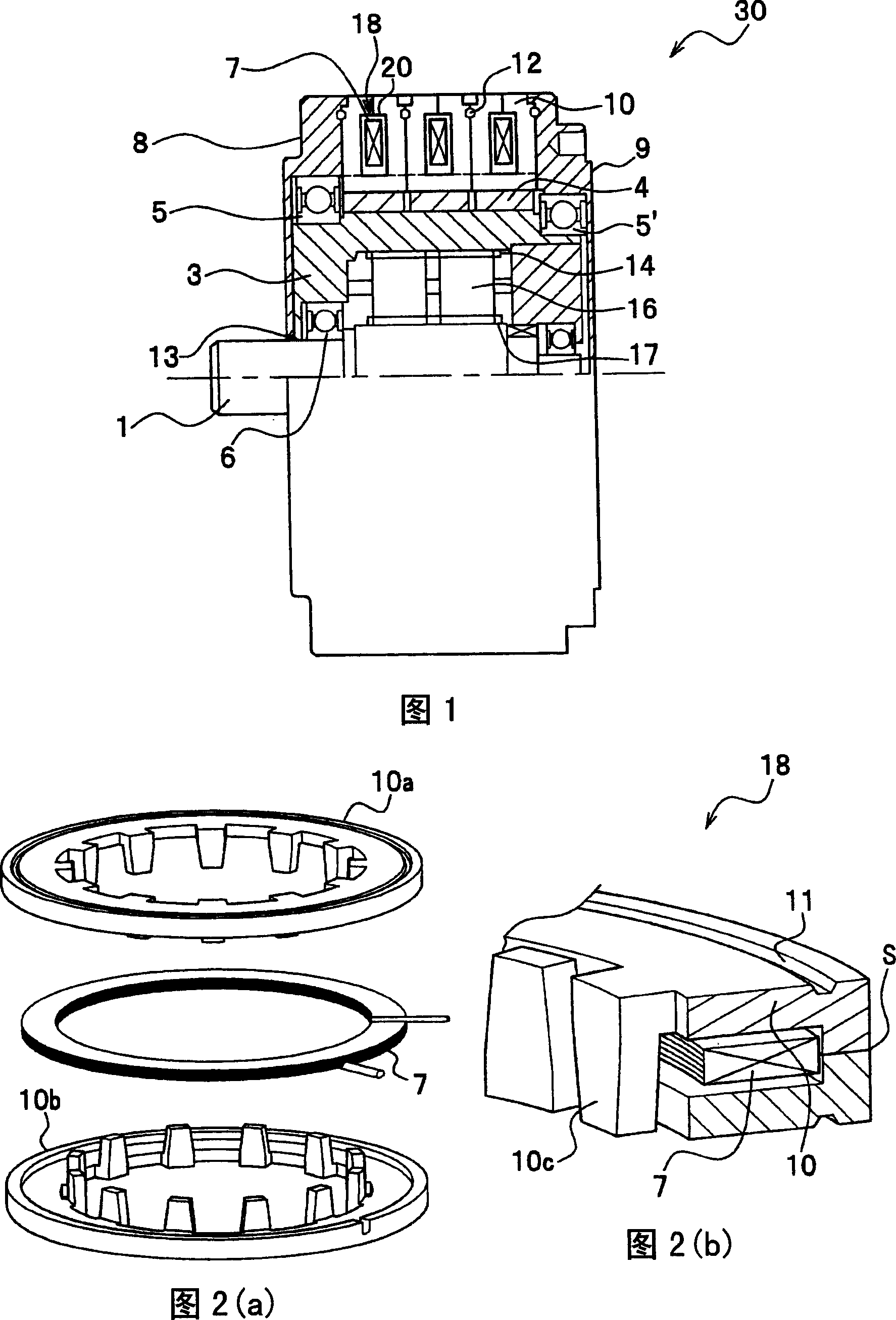
[0025] Referring to FIG. 1 and FIG. 2 , an embodiment of the present invention, that is, a rotating electrical machine with a transmission mechanism will be described. 1 is a cross-sectional view of a geared motor 30 that is a rotating electric machine with a speed change mechanism, and FIG. 2 is a perspective view showing a claw core 10 used in a stator of the geared motor 30 .

[0026] In FIG. 1 , the main structure of the deceleration motor 30 of this embodiment includes: three stators composed of field coils 7 arranged inside the annular claw-tooth iron core 10; a rotating shaft 3 of a cylindrical rotor 4; and a transmission mechanism (described later) provided inside the rotating shaft 3 to reduce the rotational speed of the output shaft 1 .

[0027] In FIG. 2 , the stator 18 has: two annular claw-tooth iron cores 10a, 10b made of a soft magnetic material such as a dust core; The tooth cores 10a and 10b are configured so that the field coil 7 can be housed, and are seale...

no. 2 Embodiment approach

[0046] The above-described embodiments have been described with respect to an electric motor as a rotating electric machine, but may be configured as a drive device using the electric motor. An automotive machine or a mobile robot as shown in Fig. 7 is considered as an example of a driving device.

[0047] By using the arm joints of a mobile body such as a mobile robot (self-propelled robot) shown in FIG. 7 that require a large torque for rotation, the weight of the mobile body can be reduced and the battery life of the mobile body can be ensured. On the mobile robot 31, a geared motor 30 is mounted on a main body that can move in the front and rear directions by means of wheels 33. The geared motor 30 rotates the rotating arm 32a in the horizontal direction, and the other geared motor built in the rotating arm 32a rotates it. The arm 33b rotates in the horizontal direction.

[0048] In addition, in automobile machines, since multiple electric motors are used on each machine,...


PUM


Abstract

A rotating electrical machine with a transmission, comprises a stator including a field coil arranged annularly, a cylindrical-shaped rotor, which rotates within the stator, transmissions provided within the cylindrical-shaped rotor, and housings to contain at least the rotor, the transmissions, and lubricating oil, and wherein the stator comprises the annular field coil and an annular core, in which the annular field coil and an organic material are contained and on an inner peripheral surface of which are provided a plurality of projecting claws.

Description

technical field [0001] The present invention relates to a rotating electric machine with a speed change mechanism, and a drive device using the same. The electric rotating machine with a speed change mechanism includes a core provided with a plurality of teeth. Background technique [0002] Electric motors are used as driving machines to convert electrical energy in industries, home appliances, automobiles, etc. into mechanical output. Electric motors serving as power machines in these fields are generally required to be small in size and high in torque. [0003] As a method of increasing the output torque, it is conceivable to amplify the torque by a reduction mechanism (transmission mechanism). According to this method, with a motor having the same gap (gap) magnetic flux density and the same relative area, the rotation speed of the motor can be increased and the output can be increased. This method is generally used in an application having a large torque, and there is ...

Claims


Application Information

Patent Timeline
Patent Type & Authority Applications(China)
IPC IPC(8): H02K7/116
CPCH02K3/44H02K7/06H02K5/10H02K5/128H02K21/145H02K7/116H02K1/145
Inventor 榎本裕治伊藤元哉正木良三大岩昭二石原千生
Owner HITACHI IND EQUIP SYST CO LTD
Why Eureka
Try Eureka