Illuminated keyboard

a key member and illuminated technology, applied in the field of keys, can solve the problems of straining the eyes of the keyboard operator, difficulty in recognizing the symbol appearing on the top of the key member, and difficulty in memorizing the keyboard operator, so as to reduce power consumption

Inactive Publication Date: 2018-07-03
SHIPMAN MICHAEL
View PDF76 Cites 18 Cited by
  • Summary
  • Abstract
  • Description
  • Claims
  • Application Information

AI Technical Summary

Benefits of technology

[0018]An additional construction of the luminescent sheet can be obtained from MKS, Inc. located in Bridgeton, N.J., USA under the trademark designation Quantaflex™. The Quantaflex™ material is an electroluminescent lamp including luminescent phosphors embedded in the dielectric medium of a capacitor constructed in the form of a sheet. Electrodes, including at least one translucent electrode, form the top and bottom layers of the Quantaflex™ material. Upon application of an alternating current to the electrodes, the phosphors give off photons producing light in the visible spectrum. An advantage of the Quantaflex™ material is that the phosphors can be selectively encapsulated between the electrode layers of the luminescent sheet so as to selectively produce patterns of light emitted from the luminescent sheet. For example, for application with the present invention, it is preferred that the Quantaflex™ material be constructed to produce light only below and / or immediately adjacent to the key members so as to reduce power consumption.
[0042]Preferably, substantial portions of the keyboard and key members are coated on their exterior surfaces with a reflective opaque coating such as paint or the like where light is not intended to be emitted from their exteriors. More particularly, it is preferred that the key members and upper clamshell member are coated with a reflective paint for reflecting visible light, which would ordinarily be emitted from the key members and upper clamshell member or substantially absorbed by a substantially non-reflective material. Thus, traditional non-reflective paints and coatings such as dark grey, black or blue are preferably avoided. Meanwhile, diffuse reflective coatings such as light grey, white, and silver are preferred, as are coherent reflective coatings such as metallic silver, metallic gold and other shiny metallic colors. Alternative substantially reflective coatings can be selected by those skilled in the art without undue experimentation. In practice, much of the visible light, which would ordinarily be lost, is reflected in either a diffuse or coherent manner back into the upper clamshell member or key members until projected from the tops of the key caps to provide enhanced luminosity of the characters formed on the key caps.
[0044]Accordingly, it is an object of the present invention to provide an improved light distribution construction, such as a light guide, which is less expensive than previous designs.
[0047]It is thus an object of the present invention to provide an inexpensive and simple way to construct a keyboard having illuminating indicia or keys.
[0049]Moreover, it is an object of the present invention to provide a keyboard having illuminated indicia or key members which does not require routing of fiber optic cables to each key member.

Problems solved by technology

A problem with prior art keyboards is that it is often difficult to discern the symbol appearing on the top of the key member under poor lighting conditions.
This causes the keyboard operator to memorize the key locations or to strain their eyes to operate the keys of the keyboard under low light conditions.
This has become a much greater problem in present day society as keyboards have become necessary for everyday use and as keyboard use is not limited primarily to operation by workers in business offices as in the past.
Often these places provide limited light making it difficult for keyboard operators to quickly and easily operate the keyboard.
Unfortunately, it is extremely difficult to route fiber optics to the keyboard keys of today's computer systems.
For example, it would be particularly difficult to route fiber optic cables and provide a light source to the key members of today's notebook computers and palm-sized computer systems.
In addition, the light sources for use with prior art backlit keyboards require substantial power and in some cases, a fan for cooling which draws additional power.
These constructions are prohibitive for portable computers such as laptop and notebook computers which draw on the power of a rechargeable battery and where power is at a premium.

Method used


Image

  • Illuminated keyboard
  • Illuminated keyboard
  • Illuminated keyboard

Examples


Embodiment Construction

[0082]While the present invention is susceptible of embodiment in various forms, as shown in the drawings, hereinafter will be described the presently preferred embodiments of the invention with the understanding that the present disclosure is to be considered as an exemplification of the invention, and is not intended to limit the invention to specific embodiments illustrated.

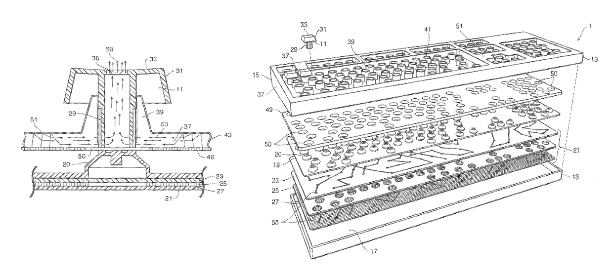
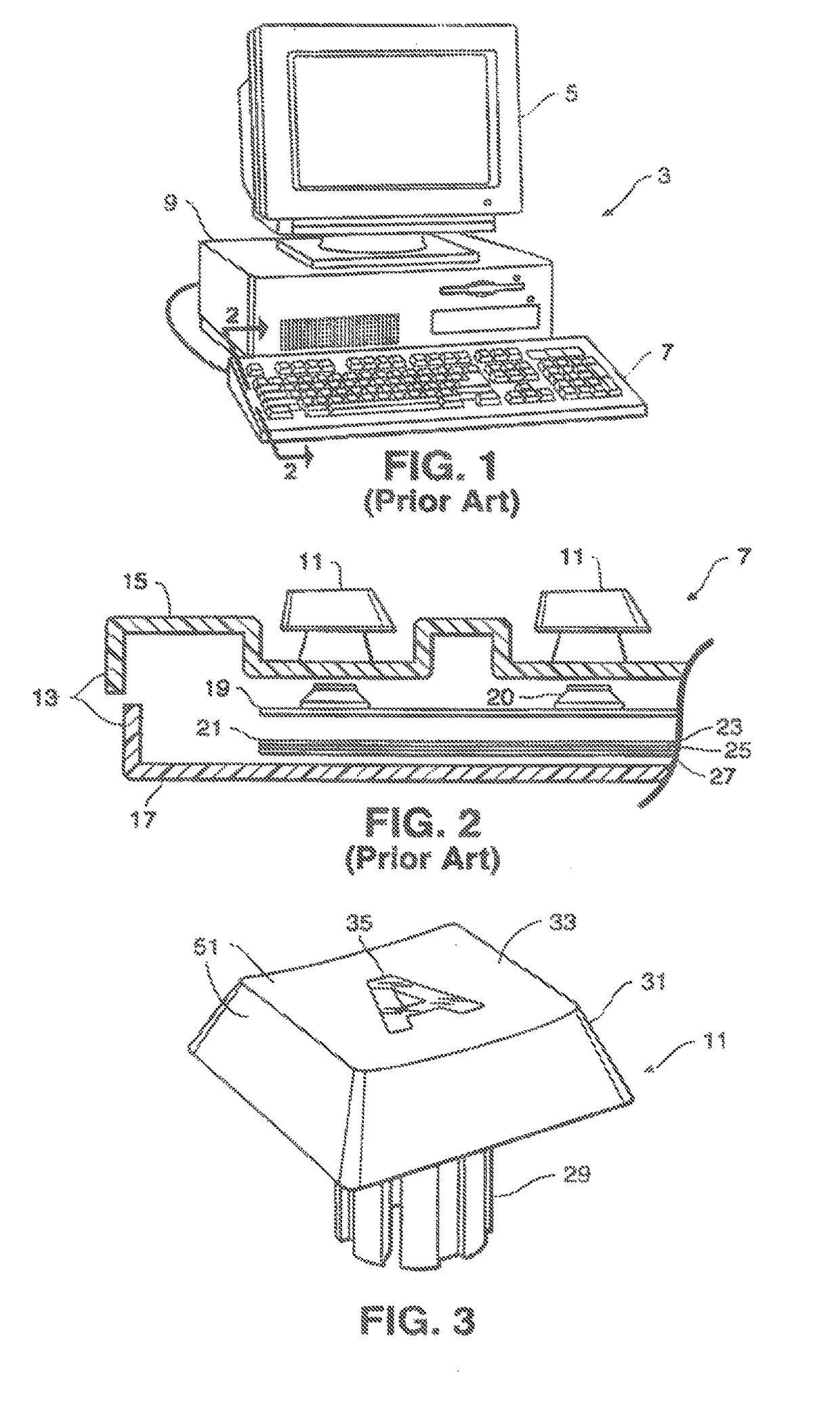
[0083]Referring to FIGS. 1-3, keyboards are required to operate numerous apparatus including computers, typewriters and personal organizers, as well as aircraft and vehicular instrument panels. A typical prior art keyboard 7 is shown in FIG. 1 for use with a computer 3. The computer 3 also includes a central processing unit 9 and monitor 5. By pressing key members 11 on the keyboard 7, one sends signals to the central processing unit 9 instructing the computer 3 to perform various functions.

[0084]As shown in FIG. 2, a typical keyboard 7 includes a housing 13 comprising an upper clamshell member 15 and lower cl...


PUM


Abstract

A light guide is provided for illuminating innumerable constructions, but which is ideally suited for illuminating the keys of a keyboard. The light guide includes a translucent planar plate having a top, a bottom and sides. Further, the light guide includes one or more cavities which project upwardly into the translucent plate from its bottom surface. The cavities are hollow or filled with a translucent material so that the translucent plate and the one or more cavities form translucent interfaces where the cavities interface with the plate. The light guide also includes a reflector which covers the plate bottom and cavity openings. Light produced by a light source, preferably in the form of one or more LEDs, is transmitted to and through the translucent plate until striking the plate-cavity interfaces where the light is refracted into the cavities' interior or reflected upwardly to the plate's upper surface.

Description

RELATED APPLICATIONS[0001]This application is a continuation application of U.S. patent application Ser. No. 14 / 541,908 filed Nov. 14, 2014, which in turn is a continuation application of U.S. Ser. No. 13 / 374,771 filed on Jan. 12, 2012, now U.S. Pat. No. 8,890,720 issued Nov. 18, 2014, which in turn is a continuation application of U.S. patent application Ser. No. 12 / 386,075 filed on Apr. 13, 2009, which in turn is a continuation-in-part of U.S. patent application Ser. No. 11 / 974,670 filed Oct. 15, 2007, which in turn is a continuation-in-part application of U.S. patent application Ser. No. 11 / 038,308 filed Jan. 18, 2005, now U.S. Pat. No. 7,283,066 issued Oct. 16, 2007, which in turn is a continuation-in-part application of U.S. patent application Ser. No. 10 / 294,396 filed on Nov. 14, 2002, now U.S. Pat. No. 6,918,677 issued Jul. 19, 2005, which in turn is a continuation-in-part application of U.S. patent application Ser. No. 09 / 899,960 filed on Jul. 6, 2001, now abandoned, which i...

Claims


Application Information

Patent Timeline
Patent Type & Authority Patents(United States)
IPC IPC(8): H03K17/94H04L17/02H01H9/00G08C19/12H03M11/00G06F3/02G06F3/023G06F3/00G09G5/00B41J5/00
CPCG06F3/0238G06F3/0202H01H13/83H01H2219/062
Inventor SHIPMAN, MICHAEL
Owner SHIPMAN MICHAEL
Why Eureka
Try Eureka