
Interactive lighting control system and method

a lighting control and interactivity technology, applied in the direction of lighting equipment, lighting sources, electrical equipment, etc., can solve the problem of difficult to trace an effect on a location back to the light source, and achieve the effect of improving the control of the lighting infrastructur

Active Publication Date: 2018-07-03
SIGNIFY HLDG BV
View PDF36 Cites 6 Cited by
  • Summary
  • Abstract
  • Description
  • Claims
  • Application Information

AI Technical Summary

Benefits of technology

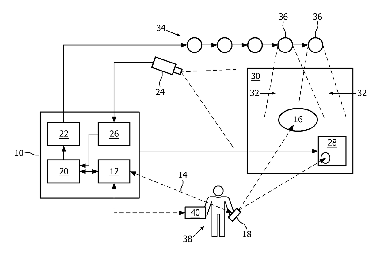
[0007]A basic idea of the invention is to provide an interactive lighting control by combining a location indication device with a light effect driven approach on lighting control in order to improve the creating of light effects such as the tuning of light scenes especially with large and diverse lighting infrastructures. The effect driven approach in lighting control can be implemented by a computer model comprising a virtual representation of a real environment with a lighting infrastructure. The virtual view may be used to map a real location to a virtual location in the virtual environment. Lighting effects available at the real location can be detected and modelled in the virtual view. Both the virtual location and the available light effects may then be used to indicate to a user light effects for selection, and to calculate control settings for a lighting infrastructure. This automated and light effect driven approach may improve the controlling of a particularly complex lighting infrastructure and offers a more natural interaction, since users only have to point to the location of the real environment, where they would like to change the light effect created by the lighting infrastructure.

Problems solved by technology

When the number of light sources is greater than 20, it can be difficult to trace an effect on a location back to the light source.

Method used


Image

  • Interactive lighting control system and method
  • Interactive lighting control system and method
  • Interactive lighting control system and method

Examples


Embodiment Construction

[0048]In the following, functionally similar or identical elements may have the same reference numerals. The terms “lamp”, “light” and “luminary” describe the same.

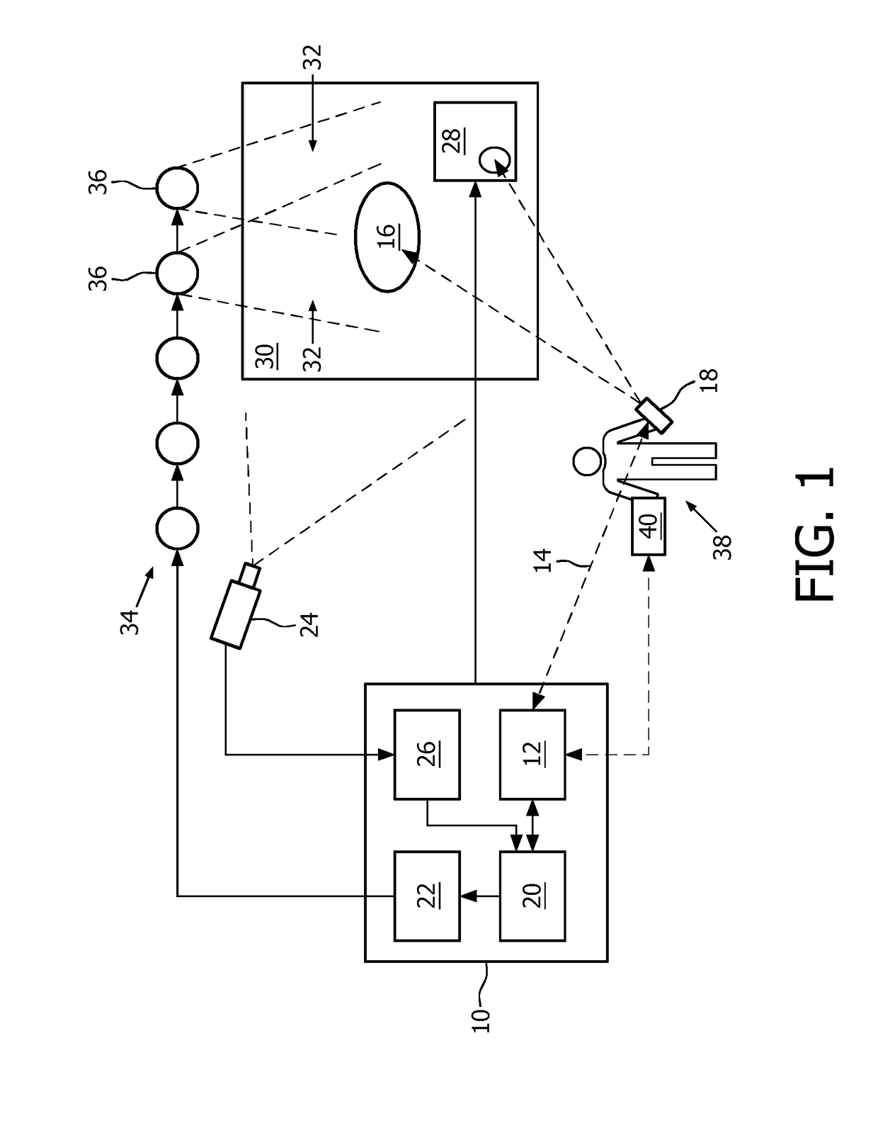
[0049]FIG. 1 shows an interactive lighting control system 10 comprising an interface 12, for example a wireless transceiver being adapted for receiving wirelessly data from an input device 18, a light effect controller 20, a light effect creator 22, and a video processing unit 26 for processing video data captured with a camera 24 connected to the interactive lighting system 10. The interactive lighting control system 10 is provided for controlling a lighting infrastructure 34 comprising several lamps 36 installed in a real environment such as a room with a wall 30. The system 10 may be implemented by a computer executing software implementing the modules 20, 22 and 26 of the system 10. The interface 12 may then be for example a Bluetooth™ or a WiFi transceiver of the computer. The system 10 may further be connected with ...


PUM


Abstract

Interactive lighting control system (and method) for controlling and creating of light effects such as the tuning of light scenes based on location indication received from an input device. A basic idea of the claimed system is to provide an interactive lighting control by combining a location indication with a light effect driven approach in lighting control in order to improve the creating of light effects such as the tuning of light scenes especially with large and diverse lighting infrastructures. The claimed interactive lighting control system (10) comprises—an interface (12) for receiving data (14) indicating a real location (16) in a real environment from an input device (18), which is adapted to detect a location in the real environment by pointing to the location, and for receiving data related to a light effect (32) desired at the real location, and—a light effect controller (20) for mapping the real location to a virtual location of a virtual view of the real environment and determining light effects available at the virtual location.

Description

TECHNICAL FIELD[0001]The invention relates to interactive lighting control, particularly to the controlling and creating of light effects such as the tuning of light scenes based on location indication received from an input device, and more particularly to an interactive lighting control system and method for light effect control and creation with a location indication device.BACKGROUND ART[0002]Future home and current professional environments will contain a large number of light sources of different nature and type: incandescent, halogen, discharge or LED (Light Emitting Diode) based lamps for ambient, atmosphere, accent or task lighting. Every light source has different control possibilities like dimming level, cold / warm lighting, RGB or other methods that change the effect of the light source on the environment.[0003]Almost all of the control paradigms in lighting are lamp driven: the user selects a lamp, and operates directly on the controls of the lamp by modifying the dimmin...

Claims


Application Information

Patent Timeline
Patent Type & Authority Patents(United States)
IPC IPC(8): H05B37/02
CPCH05B37/0272H05B47/19
Inventor ENGELEN, DIRK VALENTINUS RENEKESSELS, ANGELIQUE CARIN JOHANNA MARIA
Owner SIGNIFY HLDG BV
Learn More