Reconfigurable wireless data center network using free-space optics

a wireless data center and free-space technology, applied in the field of data center network design and management, can solve the problems of low cost, high cost, and current dc network architecture that does not provide a satisfactory solution, and achieves high data ra

Active Publication Date: 2018-07-10
THE RES FOUND OF STATE UNIV OF NEW YORK
View PDF4 Cites 1 Cited by
  • Summary
  • Abstract
  • Description
  • Claims
  • Application Information

AI Technical Summary

Benefits of technology

[0007]Exemplary embodiments of the present disclosure provide a system and method for a flexible free-space optical inter-rack network in which each top-of-rack (ToR) is equipped with reconfigurable wireless links which can connect to other ToR switches and use Free-Space Optical communications (FSO) for high data rates (tens of Gbps) over long ranges using low transmission power and with zero interference. A centralized controller can reconfigures the topology and forwarding rules to adapt to changing traffic patterns.
[0010]According to a further embodiment, the controller preconfigures an alignment of each SM to maximize a dynamic bisection bandwidth of a set of all possible candidate links between pairs of SMs.
[0011]According to a further embodiment, the dynamic bisection bandwidth is maximized by constructing an n-node random regular graph of degree mk, where n is a number of server racks, in is a number of top-mounted switch per rack, and k is a number of SMs per top-mounted switch, grouping the mk edges on each node into in sets of k edges corresponding to each of the m top-mounted switches, and for every edge connecting a pair of SMs (a, b), aligning one SM each of a and b towards each other.
[0013]According to a further embodiment, the controller preconfigures an orientation of each GM to maximize a dynamic bisection bandwidth of a set of all possible candidate links between pairs of SMs.
[0022]According to a further embodiment, the controller preconfigures an alignment of each SM to maximize a number of pairs of racks that have at least one candidate link therebetween in a set of all candidate links, and minimizing a total area of rectangular overhead mirrors, where a total number of mirrors is less than a predetermined constant r.
[0029]According to a further embodiment, the controller preconfigures an orientation of each GM to create a set of candidate links with near-optimal performance over a network of the links while minimizing usage of the overhead mirrors, where there is an orientation of a GM at each top-mounted switch so that all assigned links at the top-mounted switch are covered by the GM.

Problems solved by technology

Current DC network architectures do not provide a satisfactory solution, with respect to the above requirements.
In particular, traditional static (wired) networks are either (1) overprovisioned to account for worst-case traffic patterns, e.g., fat-trees or Clos networks, and thus incur high cost, or (2) oversubscribed, e.g., simple trees or leaf-spine architectures, which incur low cost but offer poor performance due to congested links.
However, this is infeasible on several fronts: (1) it requires very high fanout and backplane capacity, potentially nullifying the cost benefits, (2) the cabling complexity would be high, and (3) it introduces a single-point of failure.
These augmented architecture show promise, but offer only incremental improvement in performance.
Specifically, RF-wireless based augmented solutions also offer only limited performance improvement, due to inherent interference and range constraints of RF links.
Fundamentally, the challenge here is due to the large wavelengths of RF for commonly used RF bands.
In addition, regulations regarding RF bandwidth and transmit power limit achievable data rates.
Optical solutions offer high-bandwidth links and low latency, but have limited scalability, limited flexibility, and have a single point of failure.
Furthermore, all the above architectures incur high cabling cost and complexity.

Method used


Image

  • Reconfigurable wireless data center network using free-space optics
  • Reconfigurable wireless data center network using free-space optics
  • Reconfigurable wireless data center network using free-space optics

Examples


Embodiment Construction

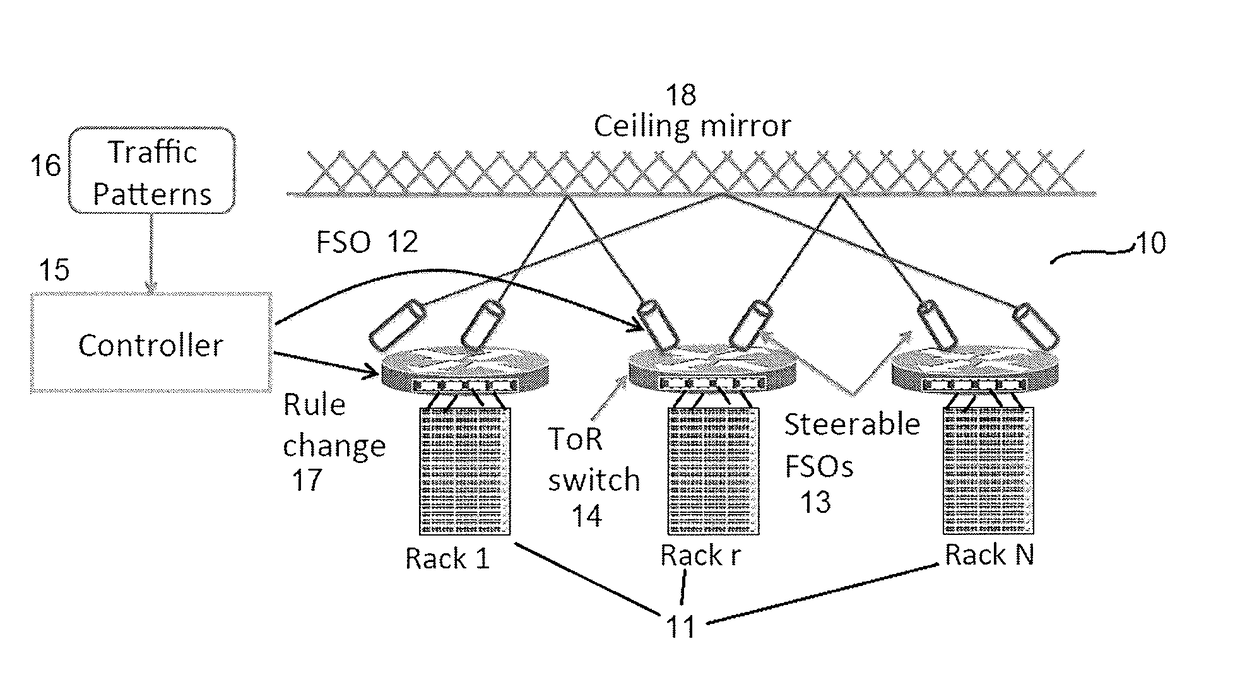
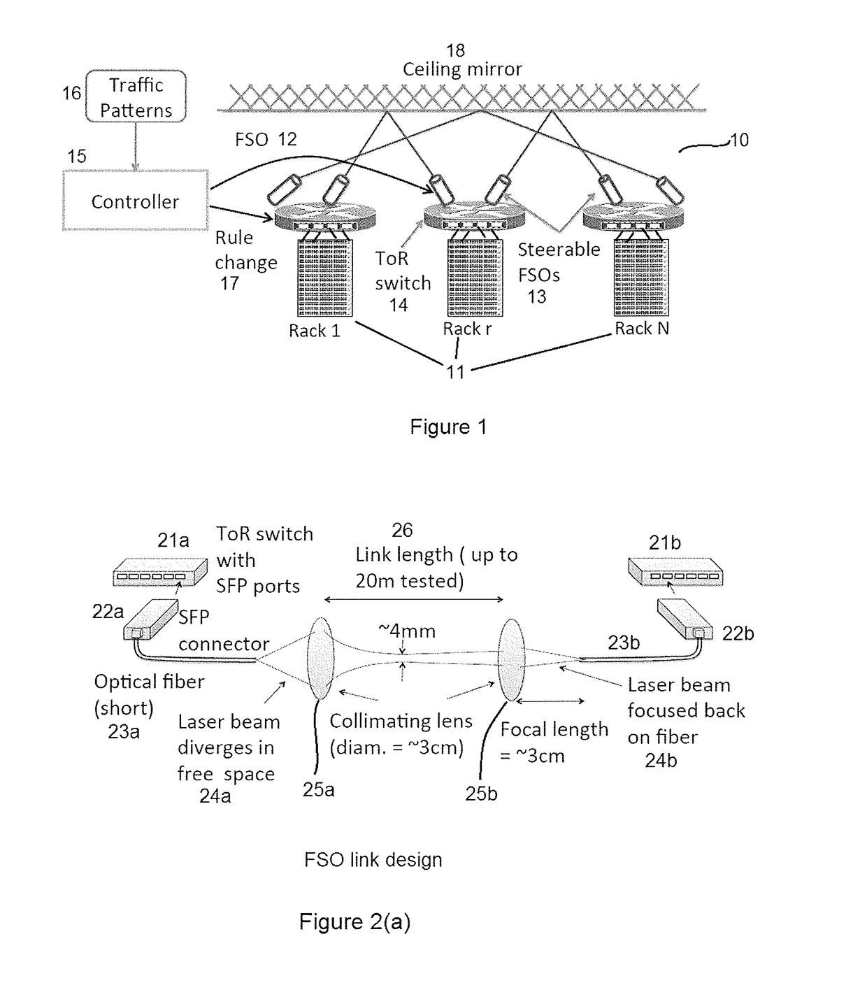
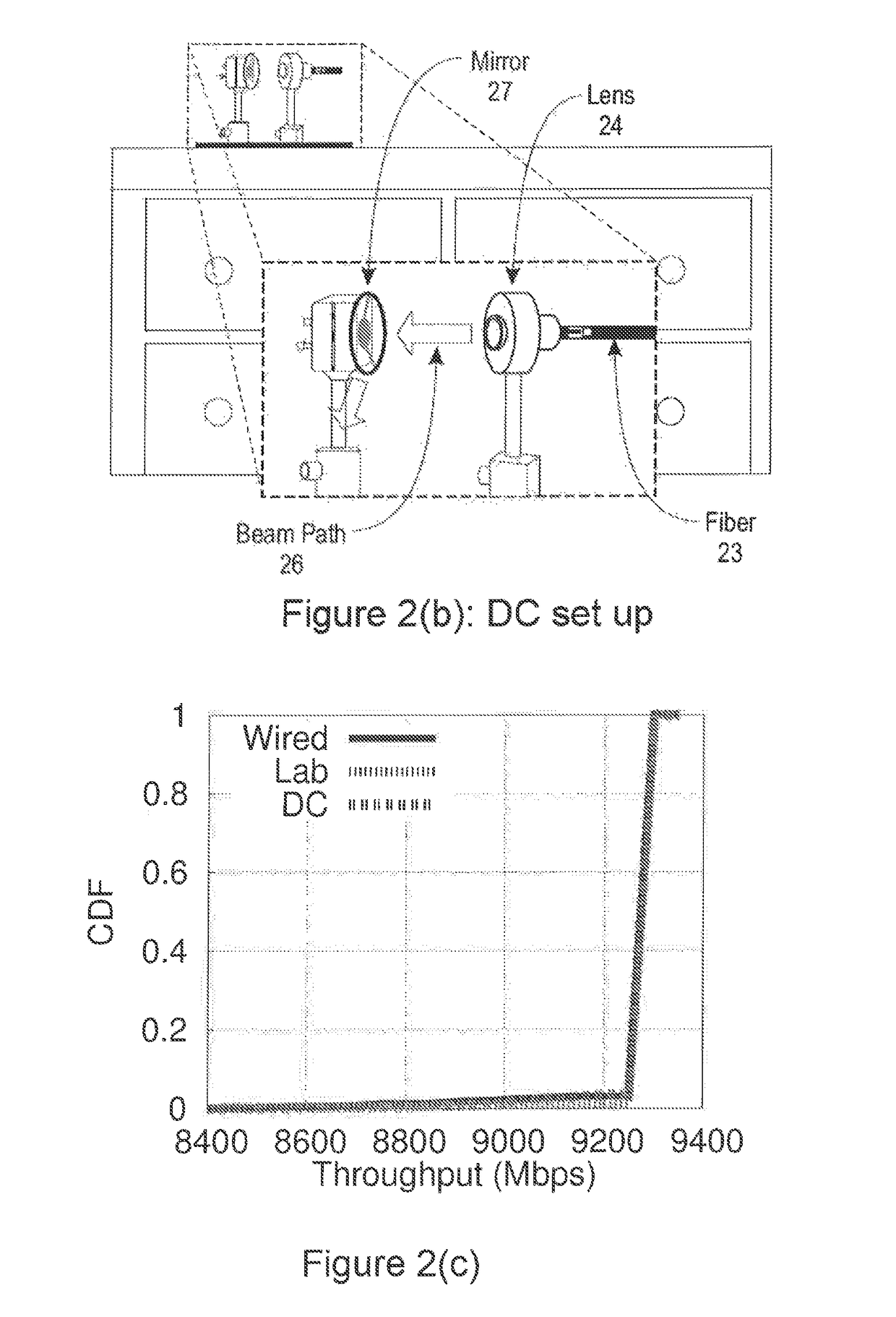
[0067]Exemplary embodiments of the disclosure as described herein generally provide systems and methods for flexible free-space optical inter-rack networks. While embodiments are susceptible to various modifications and alternative forms, specific embodiments thereof are shown by way of example in the drawings and will herein be described in detail. It should be understood, however, that there is no intent to limit the disclosure to the particular forms disclosed, but on the contrary, the disclosure is to cover all modifications, equivalents, and alternatives falling within the spirit and scope of the disclosure.

[0068]Embodiments of the present disclosure provide a DC architecture network design in which: (1) all inter-rack links are flexible; (2) all inter-rack links are wireless; and (3) the core switching backbone is eliminated.

[0069]Embodiments can provide unprecedented qualitative and quantitative benefits for DC networks. First, infrastructure cost can be reduced without compr...


PUM


Abstract

A reconfigurable free-space optical inter-rack network includes a plurality of server racks, each including at least one switch mounted on a top thereof, where each top-mounted switch includes a plurality of free-space-optic link connector, each with a free-space optical connection to a free-space-optic link connector on another top-mounted switch, a single ceiling mirror above the plurality of server racks that substantially covers the plurality of server racks, wherein the single ceiling mirror redirects optical connections between pairs of free-space-optic link connectors to provide a clear lines-of-sight between each pair of connected free-space-optic link connectors, and a controller that preconfigures a free-space optical network connecting the plurality of server racks by establishing connections between pairs of free-space-optic link connectors, and that reconfigures connections between pairs of free-space-optic link connectors in response to network traffic demands and events.

Description

CROSS REFERENCE TO RELATED APPLICATIONS[0001]This application claims priority from “Patch Panels in the Sky: A Case for Free-Space Optics in Data Centers”, U.S. Provisional Application No. 62 / 076,064 of Hamedazimi, et al., filed Nov. 6, 2014, the contents of which are herein incorporated by reference in their entirety.BACKGROUND[0002]1. Technical Field[0003]Embodiments of the present disclosure are directed to data center network design and management.[0004]2. Discussion of the Related Art[0005]Data centers (DCs) are a critical piece of today's networked applications in both private and public sectors. The key factors that have driven this trend are economies of scale, reduced management costs, better utilization of hardware via statistical multiplexing, and the ability to elastically scale applications in response to changing workload patterns. A robust datacenter network fabric is fundamental to the success of DCs and to ensure that the network does not become a bottleneck for hig...

Claims


Application Information

Patent Timeline
Patent Type & Authority Patents(United States)
IPC IPC(8): H04B10/114H04L12/24H04B10/11
CPCH04B10/11H04L41/0803H04B10/1149H04Q2011/0026
Inventor GUPTA, HIMANSHUHAMED AZIMI, NAVIDDAS, SAMIR RANJANLONGTIN, JON PATRICKSEKAR, VYASCURRAN, MAX S.
Owner THE RES FOUND OF STATE UNIV OF NEW YORK
Why Eureka
Try Eureka