Global optimization of thin film photovoltaic cell front coatings

a technology of photovoltaic cells and front coatings, applied in the field of solar cells, can solve the problems of only being able to solve approximate problems, the emerging thin-film solar cell technology presents an entirely different challenge for front coating design, and the full range of possible designs had not been explored. achieve the effect of maximizing the admittance over the selected bandwidth, and maximizing the short-circuit current of the solar cell

a technology of photovoltaic cells and front coatings, applied in the field of solar cells, can solve the problems of only being able to solve approximate problems, the emerging thin-film solar cell technology presents an entirely different challenge for front coating design, and the full range of possible designs had not been explored. achieve the effect of maximizing the admittance over the selected bandwidth, and maximizing the short-circuit current of the solar cell

US20100258174A1Inactive Publication Date: 2010-10-14MASSACHUSETTS INST OF TECH

Image

  • Global optimization of thin film photovoltaic cell front coatings
  • Global optimization of thin film photovoltaic cell front coatings
  • Global optimization of thin film photovoltaic cell front coatings

Examples


Embodiment Construction

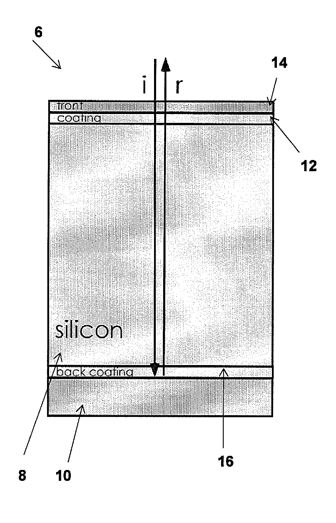
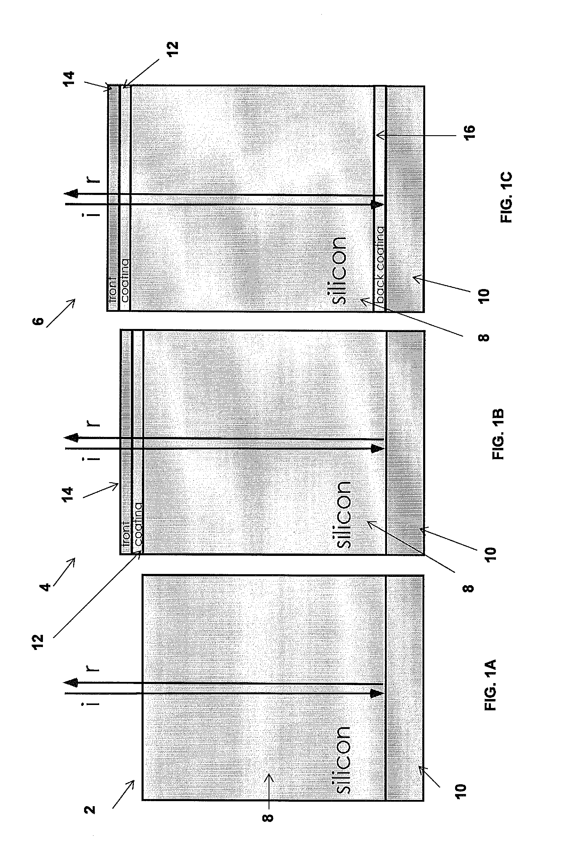
[0018]The invention provides a front-coating (FC) of a solar cell that controls its efficiency, determining admission of light into the absorbing material and potentially trapping light to enhance thin absorbers. Single-layer FC designs are well known, especially for thick absorbers where their only purpose is to reduce reflections. Multilayer FCs could improve performance, but require global optimization to design. For narrow bandwidths, one can always achieve nearly 100% absorption. For the entire solar bandwidth, however, a second FC layer improves performance by 6.1% for 256 μm wafer-based cells, or by 3.6% for 2 μm thin-film cells, while additional layers yield rapidly diminishing returns.

[0019]Emerging thin-film solar cell technology presents an entirely different challenge for front coating design. First of all, reflections from the front and back interfere over a broad range of wavelengths. Furthermore, unlike a narrow bandwidth problem, where the principles of Q-matching re...


PUM


Abstract

A solar cell includes a thin film photovoltaic material structure used in absorbing light of a selective bandwidth. A multitude of dielectric front coatings are positioned on the thin film photovoltaic material structure so as to maximize admittance over the selected bandwidth. The thicknesses and indices of each of the front coatings are chosen by a global-optimization procedure to maximize the short-circuit current of the solar cell.

Description

GOVERNMENTAL SPONSORSHIP INFORMATION[0001]This invention was made with Government support under Grant No. DMR 0819762, awarded by the National Science Foundation and also under Grant No. DAAD-19-02-D002, awarded by the Army Research Office. The Government has certain rights in the invention.BACKGROUND OF THE INVENTION[0002]The invention is related to the field of solar cells, and in particular to the global optimization of thin film photovoltaic cell front coatings.[0003]Front coatings are a critical feature of the highest-efficiency photovoltaic cells, ranging from monocrystalline silicon cells with double-layer anti-reflection (AR) coatings to thin-film CIGS cells with single-layer AR coatings. The most effective front coatings allow light over a broad range of wavelengths to enter the cell and be absorbed. This broad range of wavelengths extends from long-wave ultraviolet (around 300 nm) to the band gap wavelength (for silicon, 1108 nm). While single-layer front coating designs a...

Claims


Application Information

Patent Timeline
14 Oct 2010
Publication
US20100258174A1
IPC
H01L31/0232; H01L31/18
CPC
G02B1/115; Y02E10/50; H01L31/02168
Inventors
GHEBREBRHAN, MICHAEL; BERMEL, PETER