Dc electrical machines

a dc electrical machine and electrical motor technology, applied in the direction of electronic commutators, wind energy generation, dynamo-electric machines, etc., can solve the problems of dc electrical machine torque density limited practical performance, dc electrical machine brush commutation process complicated and complicated, and dc electrical machine arcing mode is typically destructive, so as to reduce the thermal resistance of the main wall, minimize the requirement of inter-coil insulation, and low loss operation

Active Publication Date: 2016-02-02
GE ENERGY POWER CONVERSION TECH
View PDF10 Cites 9 Cited by
  • Summary
  • Abstract
  • Description
  • Claims
  • Application Information

AI Technical Summary

Benefits of technology

[0023]According to embodiments of the present invention, the power electronic switching assembly of the electrical machine has at least first and second dc load terminals that may be connected to external equipment. For example, a single channel machine has a positive dc load terminal and a negative dc load terminal while a dual channel machine has a pair of positive dc load terminals and a pair of negative dc load terminals that can be connected in parallel to external equipment. In practice the power electronic switching assembly may be partitioned into an even number of segments, each segment having one or more switching modules and first and second local dc terminals, e.g. a local positive dc terminal and a local negative dc terminal. The first and second local dc terminals of a plurality of segments may be interconnected with one another and with the first and second dc load terminals of the power electronic switching assembly to interconnect the segments. In an embodiment, the respective local dc terminals of the power electronic switching assembly are disposed at regular intervals around the circumference of the armature as described in more detail below, the dc load terminals can be co-located within a suitable terminal enclosure to facilitate easy connection of the electrical machine to external equipment.
[0047]According embodiments of the present invention, both the circumferential distribution of the air gap flux density and the coil currents are non-sinusoidal and include low order integer harmonics. The air gap flux density and coil currents can be synchronised such that the fundamental and low order integer harmonic components of armature magneto-motive force (mmf) and air gap flux have a substantially quadrature relationship in order to maximize torque per unit armature current and to maximize torque density.

Problems solved by technology

Brush commutated dc electrical machines are known to be capable of high air gap shear stress but their practical torque density performance is limited by the brush commutation process.
However, the brush commutation process for dc electrical machines is complicated and has certain limitations.
Both under- and over-commutation arcing modes are typically destructive.
In the most basic brush commutated dc electrical machine the timing of brush commutation is critical and is severely performance limiting because ideal brush angular position varies with both armature current and speed, i.e. there is no single ideal angular position for brushgear.
As a result, the rotating commutator and stationary brushgear tend to be large and complex.
Moreover, the compoles occupy space within the electrical machine that could otherwise be used to increase the total air gap flux and torque density.
Such electrical machines have increased torque density and high efficiency but are known to produce undesirable torque pulsations.
They also cannot employ the near ideal relationship between rotor and stator space harmonics described above.
More sophisticated static frequency converters have been used to allow the torque pulsations of the LCI to be substantially eliminated but the converters are complex and are less efficient.
As line voltage rating increases, such converters become increasingly complex and it is exceptional for them to be rated at greater than 6.6 kV.
A possible shortcoming of electronically commutated electrical machines is that they are not inherently suited to high voltage dc operation since it is necessary to use series-connected semiconductor power devices and to insulate the main wall of the armature winding for high voltage ac stresses—note that the dominant voltage stress in the armature insulation is ac since each terminal in the armature winding is sequentially connected to positive and negative dc terminals.

Method used


Image

  • Dc electrical machines
  • Dc electrical machines
  • Dc electrical machines

Examples


Embodiment Construction

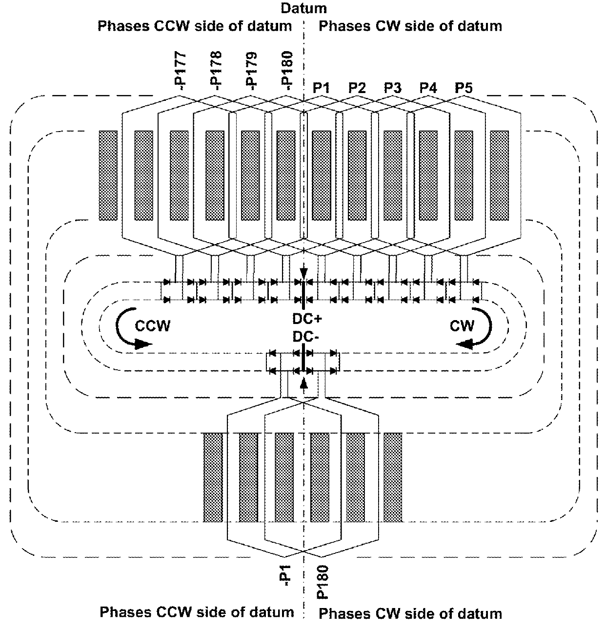
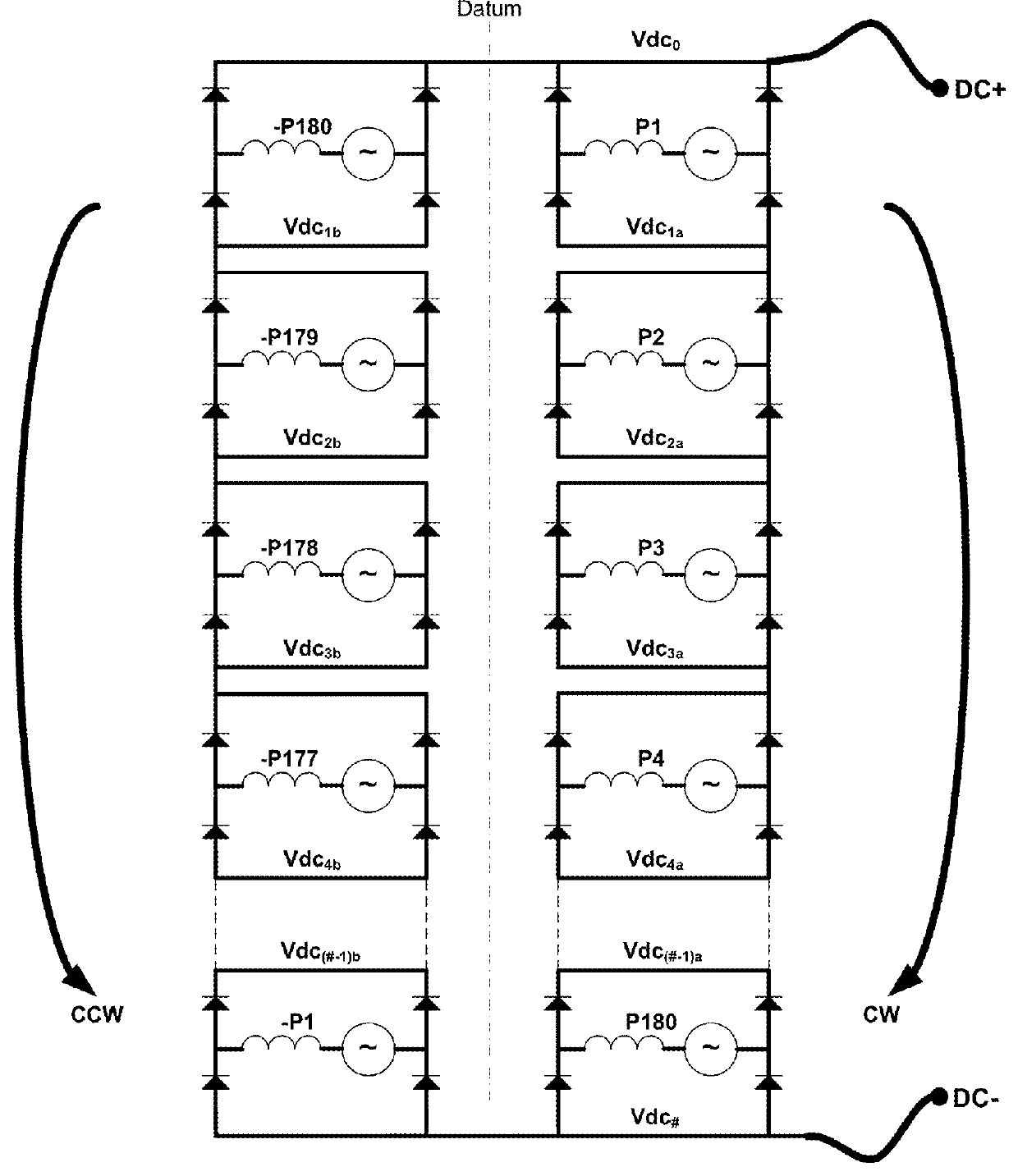
[0067]A dc electrical machine according to an embodiment of the present invention is shown schematically in FIGS. 1, 2, and 3. A dc electrical machine according to an embodiment of the present invention is shown schematically in FIGS. 4, 5, and 6. It will be readily appreciated that the rotor and much of the stator have been omitted from FIGS. 1 and 4 for clarity.

[0068]In embodiments, the stator (or armature) assembly of the electrical machine has 360 winding slots (Ns=360) for receiving the coils of the stator winding. In an embodiment, the stator winding includes 360 two-layer coils. In an embodiment, the stator winding includes 180 single-layer coils. Although not shown, the stator could have an odd number of winding slots or a tooth concentrated winding where each coil is wound around a stator tooth.

[0069]According to an embodiment, a datum is provided by the co-located local positive dc terminals Vdco of first and second segments (corresponding to first and second dc circuits) ...


PUM


Abstract

A dc electrical machine with a large number of phases. The machine includes a rotor and a stator assembly. The rotor has Np rotating field poles. The stator has Ns winding slots, where Ns / Np is a non-integer ratio. A stator winding includes a plurality of coils received in the winding slots and defines a plurality of stator phases. A power electronic switching assembly includes first and second dc load terminals that can be connected to external equipment and a plurality of switching modules. Each switching module includes power electronic devices and is connected to a respective stator coil. A first proportion of the switching modules are connected together in series between the first and second dc load terminals and a second proportion of the switching modules are connected together in series between the first and second dc load terminals to define two parallel dc circuits.

Description

FIELD OF THE INVENTION[0001]Embodiments of the present invention relate to dc electrical machines, and in particular to machines with high torque density and high power density, which are efficient and reliable, and are simple to install and commission.BACKGROUND OF THE INVENTION[0002]A dc rotating electrical machine typically includes a rotor surrounded by a wound stator. A rotor connected commutator with copper segments and stationary brushgear are used to control the commutation of current in the rotor winding based on the angular position of the rotor. Brush commutated dc electrical machines are known to be capable of high air gap shear stress but their practical torque density performance is limited by the brush commutation process. The stationary brushgear and rotating commutator converts the dc terminal voltage of the electrical machine into a polyphase ac voltage that rotates within the armature winding in a direction and at a speed that causes the armature magneto-motive fo...

Claims


Application Information

Patent Timeline
Patent Type & Authority Patents(United States)
IPC IPC(8): H02K11/00H02P25/22H02K3/28H02P6/14
CPCH02K11/33H02K3/28H02P6/14H02P25/22H02K2213/12Y02E10/725Y02E10/72
Inventor CRANE, ALLAN, DAVID
Owner GE ENERGY POWER CONVERSION TECH
Why Eureka
Try Eureka