Charge current reduction for current limited switched power supply

a technology of current limited switched power supply and charge current, which is applied in the direction of home appliance efficiency improvement, sustainable building, and electric variable regulation, can solve the problems of reducing the maximum average power deliverable to the load, less efficiency, and more power losses, so as to maximize the efficiency of a switched power converter and maximize the average current deliverable

Active Publication Date: 2013-08-20
DIALOG SEMICONDUCTOR GMBH
View PDF21 Cites 10 Cited by
  • Summary
  • Abstract
  • Description
  • Claims
  • Application Information

AI Technical Summary

Benefits of technology

[0025]A further object of the present invention is to maximize the efficiency of a switched power converter, avoiding that it enters current limit condition for the maximum possible range of system load requirements.
[0026]Another object of the present invention is to achieve a switched power converter having the least amount of output current sub-harmonics, avoiding that it enters current limit condition, for the maximum possible range of system load requirements.
[0027]Moreover another object of the present invention is to maximize the average current deliverable from a switched power converter to a system load, avoiding that it enters current limit conditions for the maximum possible range of system load requirements.

Problems solved by technology

As shown in FIG. 3 this leads to an unsteady behavior of the output current IL characterized by the presence of sub-harmonics of the clock frequency (which could interfere with other system's component), an increased ripple which leads to more power losses and less efficiency, a reduced maximum average power deliverable to the load.
While the system requirements are normally unpredictable and heavily user's dependent, the charge current is normally settable from the system itself.

Method used


Image

  • Charge current reduction for current limited switched power supply
  • Charge current reduction for current limited switched power supply
  • Charge current reduction for current limited switched power supply

Examples


Embodiment Construction

[0040]The preferred embodiments disclose methods and systems to achieve a switched power supply supporting a battery charger and a system load, wherein a charge current is reduced when the switched power supply is close to enter current limit mode due to high system current.

[0041]Shown in FIG. 4 is the typical context of applicability of the present invention. FIG. 4 illustrates a power path of a power management unit supplying a battery operated system inclusive a battery charger and a battery. A synchronous DC-DC converter 41 is used to satisfy the current requirements of a battery operated system. It has to deliver the charge current Ichg to charger 43 while at the same time feeding a system load 42 with a current Isys dependent upon the actual system activity.

[0042]For this purposes the DC-DC converter 41 draws a current Iin from a power source 40, which must never exceed a predefined value Ilim, which is externally settable.

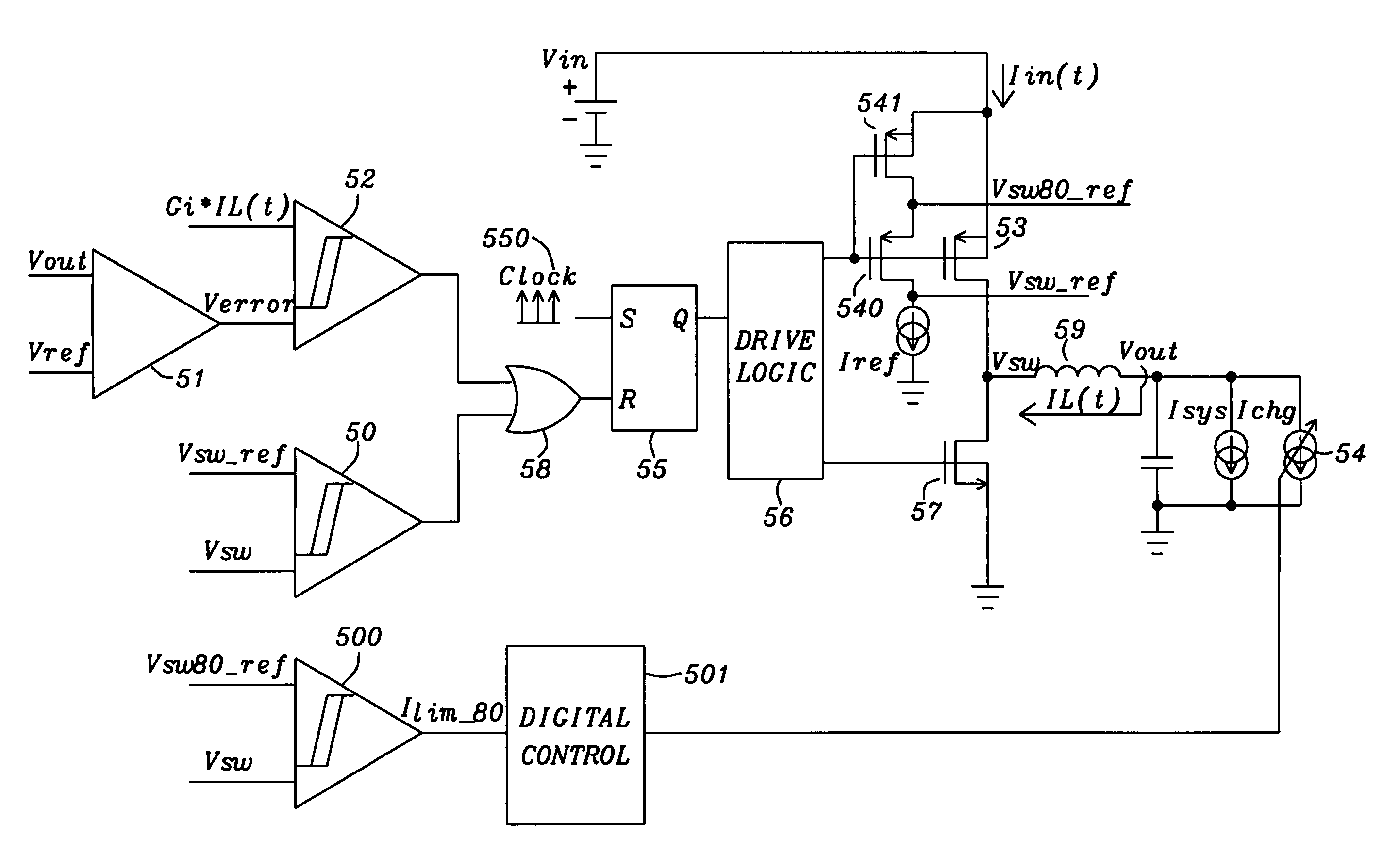
[0043]FIG. 5 shows a simplified architecture of a sync...


PUM


Abstract

Circuits and methods for a switched power converter providing charge power for at least one battery and at the same time delivering current to operate an electronic device, wherein the converter is enabled to operate out of current limit mode, for the maximum possible range of system load requirements, have been achieved. The input current of the power converter is measured within each cycle-by-cycle, i.e. within each cycle of an external clock reference and the charge current is reduced if the input current exceeds a defined portion, e.g. 80% of the maximum allowable input current. The power converter may only enter current limited operation after the charge current has been already reduced to zero. Operating out of current limit mode ensures a maximum efficiency of the converter, maximize the current deliverable to a given load and minimizes subharmonics in the output current and voltage, thereby minimizing interference with other system component.

Description

BACKGROUND OF THE INVENTION[0001](1) Field of the Invention[0002]This invention relates generally to the field of DC-to-DC converters and relates more specifically to switched power supplies converters having a programmable input current limit and a controlled limited output current in order to operate with maximum efficiency and providing a regulated power supply to battery equipped systems. The power supply is required to provide the charge current to the battery while, at the same time, being able to deliver current to the system.[0003](2) Description of the Prior Art[0004]Buck or Boost Converters find extensive use in power management applications because of their high efficiency. They can step up or down an input voltage source to a different voltage supply DC level more appropriate for a specific load.[0005]They use a storage element device (an inductor) on which energy is alternatively stored and then delivered to a load. At this purpose switches are used, whose ON and OFF st...

Claims


Application Information

Patent Timeline
Patent Type & Authority Patents(United States)
IPC IPC(8): H02J7/00
CPCH02J7/0052H02M3/158H02J2007/0059Y02B40/90H02J7/00H02J2207/20Y02B40/00
Inventor SCALDAFERRI, STEFANOMARSCHALKOWSKI, ERICWOLF, CHRISTIAN
Owner DIALOG SEMICONDUCTOR GMBH
Why Eureka
Try Eureka