Ion beam implant current, spot width and position tuning

a technology of implant applied in the field of implanter systems, can solve the problems of iwasawa being unable affecting the productivity of ion implanter systems, and simultaneously optimizing spot width, so as to maximize implant current, maximize implant current, and optimize total ion beam current

Active Publication Date: 2008-10-28
VARIAN SEMICON EQUIP ASSOC INC
View PDF16 Cites 10 Cited by
  • Summary
  • Abstract
  • Description
  • Claims
  • Application Information

AI Technical Summary

Benefits of technology

[0010]This invention provides an ion beam tuning method, system and program product for tuning an ion implanter system. The invention obtains an ion beam profile of the ion beam by, for example, scanning the ion beam across a profiler that is within an implant chamber; and tunes the ion implanter system to maximize an estimated implant current based on the ion beam profile to simultaneously optimize total ion beam current and ion beam spot width, and maximize implant current. In addition, the tuning can also position the ion beam along a desired ion beam path, which improves ion implanter system productivity and performance by reducing ion beam setup time and provides repeatable beam angle performance for each ion beam over many setups. With specific regard to reducing ion beam setup time, the invention reduces the need for parallelism and uniformity tuning because a stored corrector magnet setting and uniformity scan waveform slope array will remain constant if ion beam spot width and spot beam center position are maintained same for each ion beam over many setups.
[0011]A first aspect of the invention is directed to a method for tuning an ion beam in an ion implanter system, the method comprising the steps of: obtaining an ion beam profile of the ion beam; and tuning the ion implanter system to maximize an estimated implant current based on feedback from the profiler to simultaneously optimize total ion beam current and ion beam spot width, and maximize implant current.
[0012]A second aspect of the invention is directed to a system for tuning an ion beam in an ion implanter system, the method comprising the steps of: means for obtaining an ion beam profile of the ion beam; and means for tuning the ion implanter system to maximize an estimated implant current based on feedback from the profiler to simultaneously optimize total ion beam current and ion beam spot width, and maximize implant current.
[0013]A third aspect of the invention is directed to a computer program product comprising a computer useable medium having computer readable program code embodied therein for tuning an ion beam in an ion implanter system, the program product comprising: program code configured to obtain an ion beam profile of the ion beam; and program code configured to tune the ion implanter system to maximize an estimated implant current based on feedback from the profiler to simultaneously optimize total ion beam current and ion beam spot width, and maximize implant current.

Problems solved by technology

In particular, oversweep creates a situation in which a fraction of the entire beam is available for use, which impacts ion implanter system productivity.
In so doing, Iwasawa approximates the total ion beam current and ion beam spot width to their preferable states, but does not otherwise attempt to achieve an optimized total ion beam current and optimized ion beam spot width to maximize implant current.
More specifically, it is impossible for Iwasawa to maximize implant current because it is incapable of simultaneously optimizing total ion beam current and ion beam spot width to achieve this goal.
Iwasawa is also limited in the ability to affect these parameters because it controls only the one lens.
As a result, Iwasawa is incapable of adequately addressing the underutilization of an ion beam caused by oversweep.
Another challenge to optimizing ion implanter productivity is to minimize beam set up time.
The challenge is increased because it is common to repeatedly use the same group of ion beams for implanting different wafers.

Method used


Image

  • Ion beam implant current, spot width and position tuning
  • Ion beam implant current, spot width and position tuning
  • Ion beam implant current, spot width and position tuning

Examples


Embodiment Construction

[0024]Ion Implanter System Overview

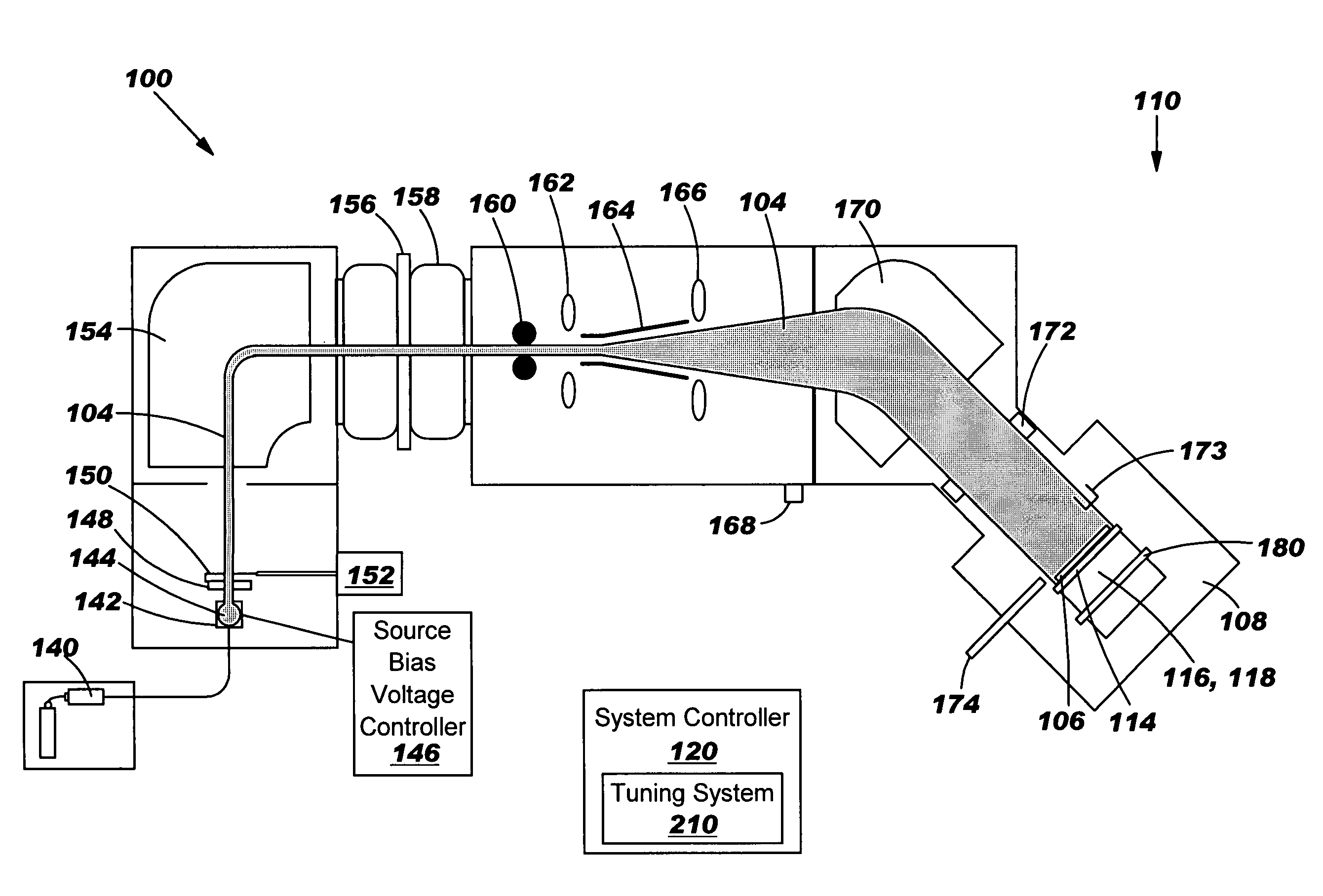
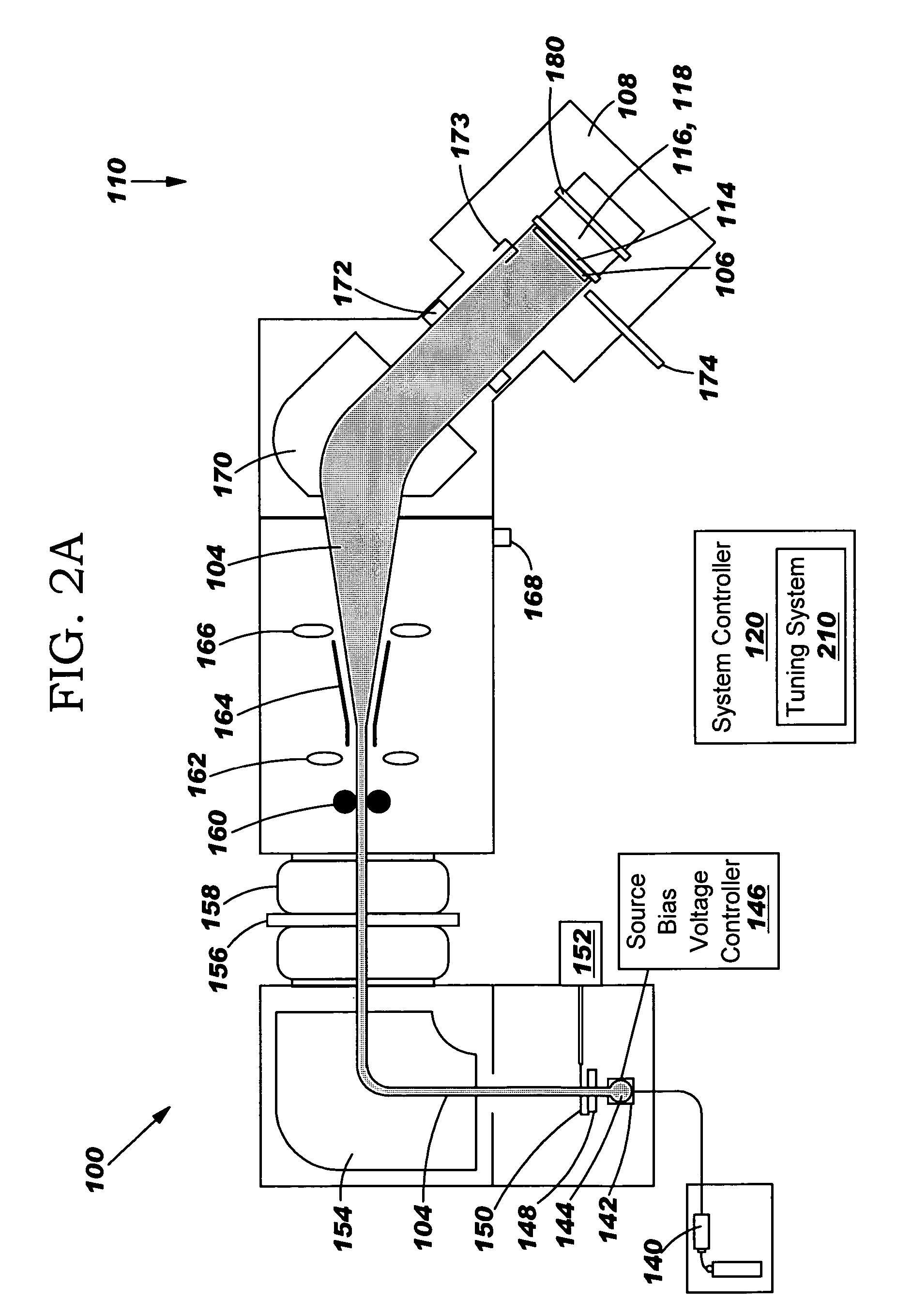
[0025]With reference to the accompanying drawings, FIG. 2A illustrates a first embodiment of an ion implanter system 100 according to the present invention. Implanter system 100 includes an ion beam generator 102 for generating and transmitting an ion beam 104 to a target 106 in an implant chamber 108. Ion beam generator 102 may be any now known or later developed ion beam generator such as those available from Varian Semiconductor Equipment Associates. Typically, target 106 includes one or more semiconductor wafers mounted to a holder 114. Characteristics of target 106 may be controlled by a holder drive assembly 116 that rotates the target 106, i.e., wafer, and a target vertical scan system position controller 118 that controls the vertical position of target 106. Drive assembly 116 and position controller 118 are both responsive to a system controller 120.

[0026]Besides the above-described components, ion beam generator 102 may include a gas flow...


PUM


Abstract

An ion beam tuning method, system and program product for tuning an ion implanter system are disclosed. The invention obtains an ion beam profile of the ion beam by, for example, scanning the ion beam across a profiler that is within an implant chamber; and tunes the ion implanter system to maximize an estimated implant current based on the ion beam profile to simultaneously optimize total ion beam current and ion beam spot width, and maximize implant current. In addition, the tuning can also position the ion beam along a desired ion beam path based on the feedback of the spot beam center, which improves ion implanter system productivity and performance by reducing ion beam setup time and provides repeatable beam angle performance for each ion beam over many setups.

Description

BACKGROUND OF THE INVENTION[0001]1. Technical Field[0002]The present invention relates generally to ion implanter systems, and more particularly, to a method, system and program product for tuning an ion implanter system to maximize ion beam implant current by using an estimated implant current, and to position the ion beam along a desired ion beam path by using a spot beam center.[0003]2. Related Art[0004]Ion implantation processes typically require a uniform and consistent dose or amount of ions to be implanted into a semiconductor wafer. Dose is generally a function of ion beam current density and time that the wafer spends in front of an ion beam. Referring to FIG. 1, conventional single wafer ion implanters typically provide an ion beam that is horizontally an electro-statically scanned spot beam 4. In order to scan a wafer 6, one conventional approach moves the wafer vertically (as shown by the three wafer 6 positions in FIG. 1) and ion beam 4 is swept horizontally back-and-fo...

Claims


Application Information

Patent Timeline
Patent Type & Authority Patents(United States)
IPC IPC(8): H01J37/317
CPCH01J37/3171H01J2237/24542H01J2237/30461H01J2237/31703H01J37/317H01J37/30H01J37/36
Inventor CHANG, SHENGWUCUCCHETTI, ANTONELLADZENGELESKI, JOSEPH P.GIBILARO, GREGORY R.MOLLICA, ROSARIONORRIS, GREGG A.OLSON, JOSEPH C.WELSCH, MARIE J.
Owner VARIAN SEMICON EQUIP ASSOC INC
Why Eureka
Try Eureka