LED lighting array for a portable task lamp

a task lamp and led technology, applied in the direction of lighting and heating apparatus, lighting support devices, printed circuit non-printed electric components association, etc., can solve the problems of limited life and a narrow focus, fluorescent lighting strips, electrical inefficiency, etc., to maximize the efficiency of disk flux, maximize led intensity, and light weight

Active Publication Date: 2008-06-19
BAYCO PRODS
View PDF6 Cites 11 Cited by
  • Summary
  • Abstract
  • Description
  • Claims
  • Application Information

AI Technical Summary

Benefits of technology

[0012]The present invention has as its object to overcome various of the shortcomings in the prior art described above. More specifically, the present invention has as its object to provide a portable task light employing a plurality of LEDs in an array which combines a novel off-axis orientation in the layout of the LEDs in the LED array with a pulsed current drive to maximize LED intensity. This combination provides a very compact, light weight task light and maximizes disk flux efficiencies at a selected task light target distance. The off-axis layout may be made adjustable in a variable emission formulation.
[0014]In one preferred embodiment of the invention, the LEDs are mounted on the planar mounting surface to form an emission plane—array of LEDs disposed in columns and electrically coupled in series. The emission axes of all the LEDs in a first column are parallel with each other and lie in one plane. The emission axes of the LEDs in an adjacent, second column are also parallel, but the plane containing the emission axes of the second column is disposed at a predetermined, non-zero angle with respect to the plane of the first column. This orientation of the LEDs provides an optimum balance at a predetermined target distance between the size of the area illuminated and the brightness of the illumination of the target.
[0015]In another preferred embodiment of the invention, the LED's are mounted on the planar mounting surface in an adjustable emission plane which allows a user to vary the directivity and intensity of the array, thereby enabling a user to minimize exclusion zones and maximize illumination at selected target distances from the task light assembly. As used in this description, “exclusion zones” refers to zones of weak illumination upon an illuminated surface that occur when the illumination pattern of multiple emitters in an array includes voids between portions of the pattern's geometry at the surface being illuminated. Preferably, a portion of the LED's, e.g., one column of LEDs, are positioned on the planar mounting surface in a predetermined off-axis orientation which maximizes disk flux efficiency of light emission from the array of LED's at a selected task light target distance. As used in this description, “disk flux efficiency” refers to how efficiently and uniformly a light beam from an individual emitter or lamp having a circular cross-section, or of an array of such light beams from multiple emitters, illuminates a specified target object or zone at a given distance.
[0017]In one illustrative embodiment of the invention, the electrical drive circuit operates directly from an AC line voltage power input, rectified by a full-wave bridge rectifier, thereby supplying pulsating direct current, which maximizes forward current to the LED's. This circuit eliminates the need for an electrical transformer component.
[0019]In a preferred embodiment of the invention, the LED's are mounted on the top surface of the circuit board and a portion of the LEDs are mounted in an off-axis orientation which maximizes disk flux efficiency of light emission from the LED's at a selected task light distance. The off-axis mounting angle of the LED's on the top surface of the circuit board results in a reduction in the number of exclusionary zones produced by the light being emitted at the selected task light distance, thereby maximizing illumination at the selected target distance.

Problems solved by technology

The prior art devices used for this purpose include battery powered flashlights that have a limited life and a narrow focus; incandescent drop-lights that feature electrically inefficient, very hot and volatile tungsten filaments; and various types of fluorescent lights.
The fluorescent lighting strips also have disadvantages, however, in that a ballast must be included in the fixture.
Prior art arrays generally are not adapted to varying their illumination patterns according to the target size or distance from the light source.
The known prior art devices have also failed to take advantage of the benefits of driving the LED array with a pulsating direct current and have thus failed to maximize the LED intensity and the light output therefrom.

Method used


Image

  • LED lighting array for a portable task lamp
  • LED lighting array for a portable task lamp
  • LED lighting array for a portable task lamp

Examples


Embodiment Construction

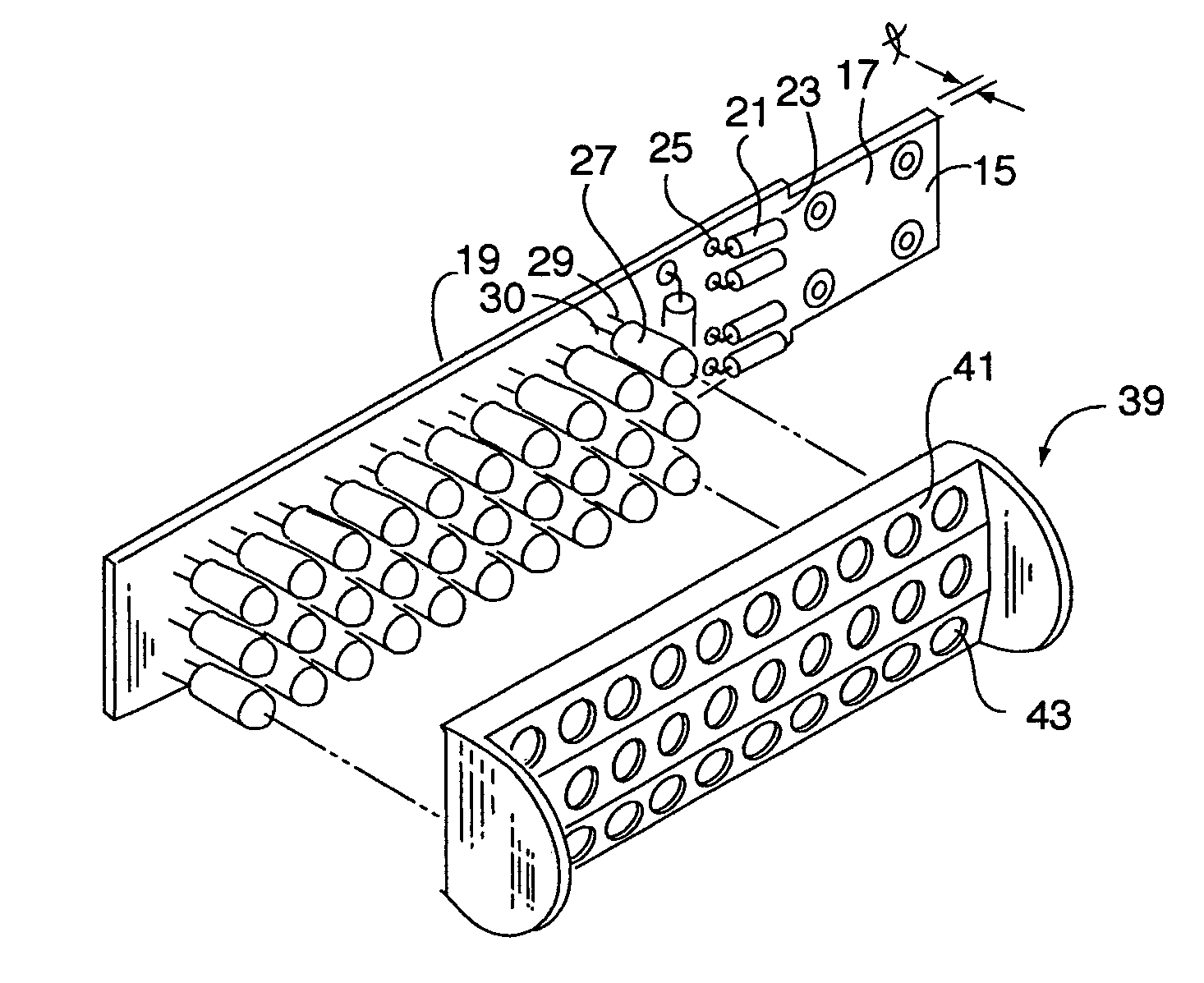
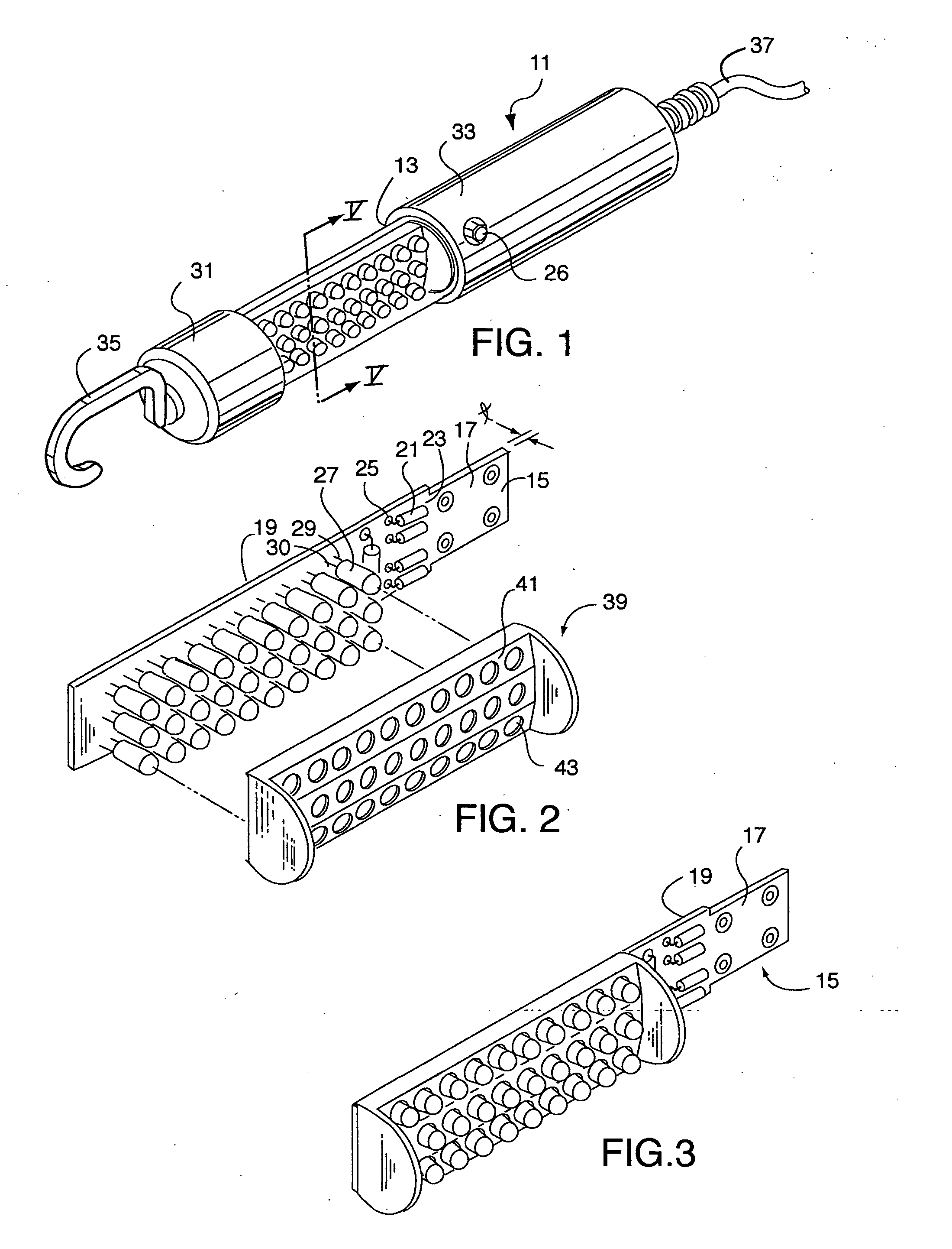
[0034]Turning to FIG. 1, there is shown an LED task light assembly designated generally as 11. The task light assembly 11 includes a rigid hollow tube 13 (FIGS. 1 and 5) that is either transparent or translucent having appropriate light transmitting optical characteristics. The material of the hollow tube 13 is preferably a suitable plastic or acrylic commercially available formulation such as a rugged and optically clear polycarbonate, polyethylene, polypropylene or polyvinyl chloride. Acrylics or polycarbonates are found to be suitable materials as they are both transparent and basically rigid and have the structural integrity necessary for the application. The tube is cylindrically shaped and has a length which is selected based upon on its practical intended use. For example, in the case of a light having an overall length of about 10 inches, the tube can be about 3½ inches in length and about 1½ inches in diameter.

[0035]As shown in FIG. 1, the rigid hollow tube 13 has disposed ...


PUM


Abstract

An LED lighting array is disclosed wherein a plurality of light emitting devices disposed in at least first and second columns are mounted on a planar mounting surface to form an emission plane. The emission axes of all the LEDs in a first column are parallel with each other and lie in a first plane. The emission axes of the LEDs in an adjacent, second column are also parallel, but a second plane containing the emission axes of the second column is disposed at a predetermined, non-zero angle with respect to the first plane. The non-zero angle is a function of the LED beam width and the distance to a lighting target. This configuration of the LEDs provides an optimum balance at a predetermined target distance between the size of the area illuminated and the brightness of the illumination of the target. In one aspect of the invention the LED lighting array includes at least first, second and third columns of LEDs. In another aspect of the invention an LED task light includes a transparent tube and an LED lighting array disposed within the tube. An electrical drive circuit associated with the mounting substrate within the tube provides pulsed direct current for driving the LED's.

Description

CROSS REFERENCE TO RELATED INVENTION[0001]This application is a Continuation of U.S. patent application Ser. No. 10 / 730,600, filed Dec. 8, 2003 and entitled “LED Lighting Array for a Portable Task Lamp, which claims priority from U.S. Provisional Patent Application No. 60 / 468,551, filed May 7, 2003, entitled “LED Drive Circuit and Mounting Array For a Portable Task Light”, by the same inventor.BACKGROUND OF THE INVENTION[0002]1. Field of the Invention[0003]The present invention relates generally to the field of electrical lighting devices and, more specifically, to a portable task light which utilizes an array of light emitting devices such as light emitting diodes (LED's). The array of LEDs may be mounted on a printed circuit board disposed within a transparent or translucent tube.[0004]2. Description of the Prior Art[0005]There is often a need to enhance area illumination by using portable lighting products. The prior art devices used for this purpose include battery powered flash...

Claims


Application Information

Patent Timeline
Patent Type & Authority Applications(United States)
IPC IPC(8): F21V21/00F21K99/00F21L14/02F21V14/02H05K1/14H05K1/18H05K3/30
CPCF21K9/00F21L14/023F21V14/02F21Y2101/02F21Y2105/005H05K2201/2027H05K1/18H05K3/301H05K2201/10106H05K2201/10484H05K1/148F21Y2115/10F21Y2107/50
Inventor NEWTON, JAMESBAYAT, BIJAN
Owner BAYCO PRODS
Why Eureka
Try Eureka