DC electrical machines

a dc electrical machine and electrical motor technology, applied in the direction of electronic commutators, wind energy generation, dynamo-electric machines, etc., can solve the problems of dc electrical machine torque density limited practical performance, dc electrical machine brush commutation process complicated and complicated, and dc electrical machine arcing mode is typically destructive, so as to reduce the thermal resistance of the main wall, minimize the requirement of inter-coil insulation, and low loss operation

Active Publication Date: 2014-03-06
GE ENERGY POWER CONVERSION TECH
View PDF4 Cites 10 Cited by
  • Summary
  • Abstract
  • Description
  • Claims
  • Application Information

AI Technical Summary

Benefits of technology

[0031]According to embodiments of the present invention, in all arrangements the switching modules will be interconnected in the dc domain so as to comply with requirements such as the minimization of inter-coil voltage under normal operating conditions, this being achieved by the appropriate positioning of the local dc terminals of like polarity immediately adjacent to one another so as to permit their direct interconnection in the dc domain, or their effective interconnection in the dc domain by external equipment. According to embodiments, dual channel machines that are operating under normal conditions, the external equipment is responsible for minimizing the inter-coil voltages, i.e. the voltage between immediately adjacent but non-interconnected pairs of local dc terminals. However, it will be readily understood that a dual channel machine has two pairs of independently galvanically isolated dc load terminals and that these could settle at different common mode voltages under fault conditions. Consequently, a substantial fault voltage could be developed between respective local dc terminals that are positioned immediately adjacent to one another.
[0032]According to embodiments of the present invention, the main wall insulation for the coils will be dominated by a dc voltage component and inter-coil insulation requirements are minimized in single channel machines under all operating conditions and in dual channel machines under normal operating conditions. The main wall insulation can be inherently self-stress grading within its bulk and over its surfaces under conditions wherein the voltage stress is predominantly dc in nature with substantially less significant ac components being present. More particularly, the main wall insulation can contain nano-particle non-linear stress grading throughout its bulk, allowing a relatively thin main wall to be employed and thereby reducing main wall thermal resistance while providing partial discharge-free and low loss operation. Inter-coil voltages are particularly low and comprise dc and ac components that are insufficient to cause partial discharge, thereby allowing endwinding insulation to be simplified. Inter-turn voltages within each coil are comparable to those in conventional electrical machines and conventional inter-turn insulation can be used.
[0033]According to embodiments of the present invention, since the coils are connected together in the dc domain, many phases can be provided without having to use complex endwinding interconnections, ac terminations and ac insulation systems. More particularly, a dc electrical machine according to embodiments of the present invention may have many phases per slot per pole. In permanent magnet generators it is known to limit the number of slots per pole in order to reduce the effects of armature reaction and/or to reduce the stator back of core radial depth requirement, and the present invention allows these benefits to be retained while still having a high number of armature phases. Conventional permanent magnet generators typically have three slots per pole (n=3) and the number of armature phases of conventional ac interconnected windings in such machines is normally limited to three or six. However, a permanent magnet generator according to an embodiment of the present invention having approximately three slots per pole would have many (e.g. >70) armature phases.
[0034]According to embodiments of the present invention, the coils can be connected in the dc domain to provide phase cancellation of coil voltage harmonics thereby minimizing dc terminal voltage ripple and minimizing circulating currents that flow in the parallel dc circuits between the first and second dc load terminals and, where appropriate, in the parallel dc circuits between the other additional dc load terminals, e.g. in a dual channel machine. The dc terminal voltage of each switching module is dominated by the second harmonic of the associated coil voltage but open circuit coil voltage and current/impedance related voltage harmonics will be synchronously trans...

Problems solved by technology

Brush commutated dc electrical machines are known to be capable of high air gap shear stress but their practical torque density performance is limited by the brush commutation process.
However, the brush commutation process for dc electrical machines is complicated and has certain limitations.
Both under- and over-commutation arcing modes are typically destructive.
In the most basic brush commutated dc electrical machine the timing of brush commutation is critical and is severely performance limiting because ideal brush angular position varies with both armature current and speed, i.e. there is no single ideal angular position for brushgear.
As a result, the rotating commutator and stationary brushgear tend to be large and complex.
Moreover, the compoles occupy space within the electrical machine that could otherwise be used to increase the total air gap flux and torque density.
Such electrical machines have increased torque density and high efficiency but...

Method used


Image

  • DC electrical machines
  • DC electrical machines
  • DC electrical machines

Examples


Embodiment Construction

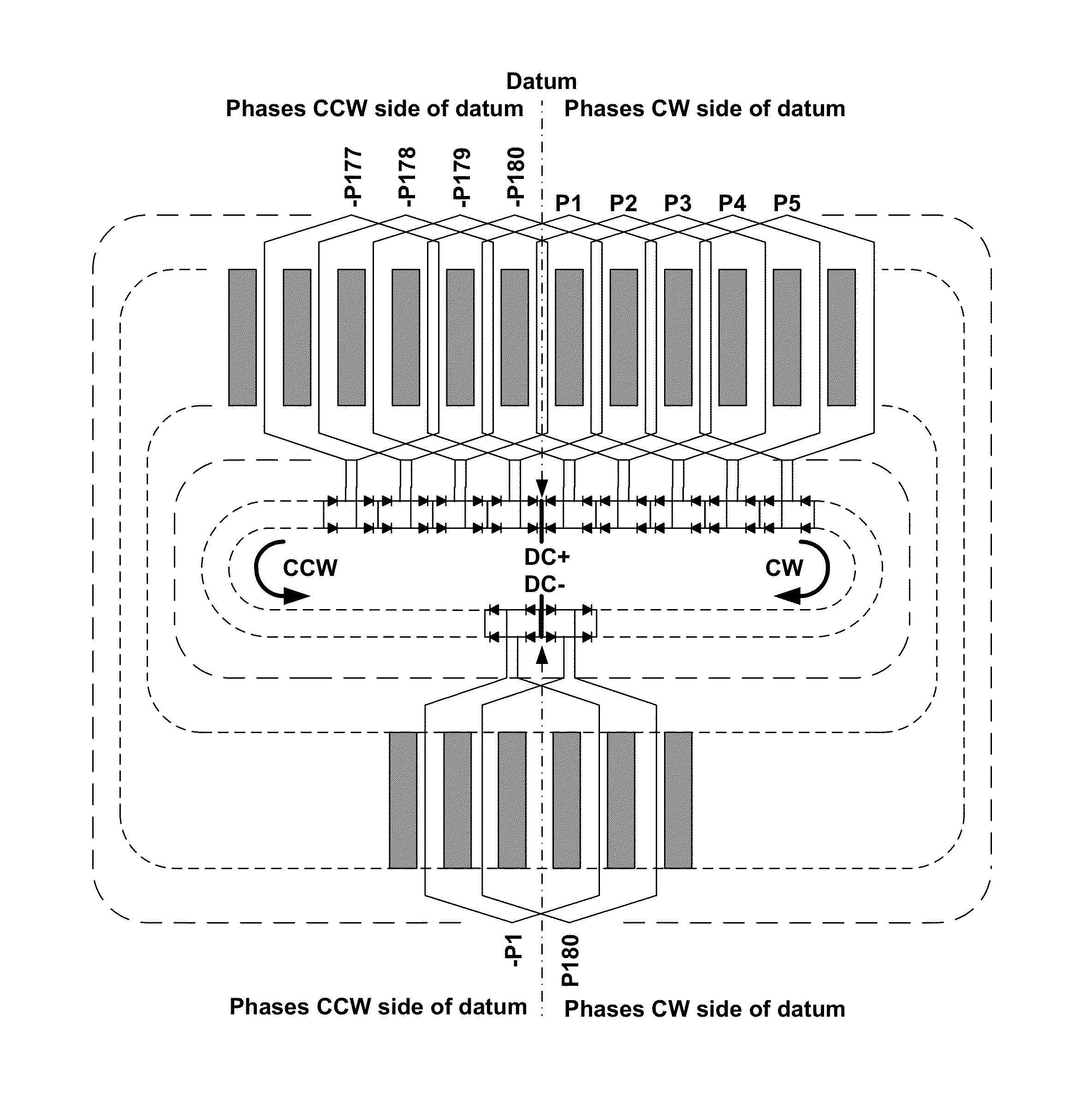
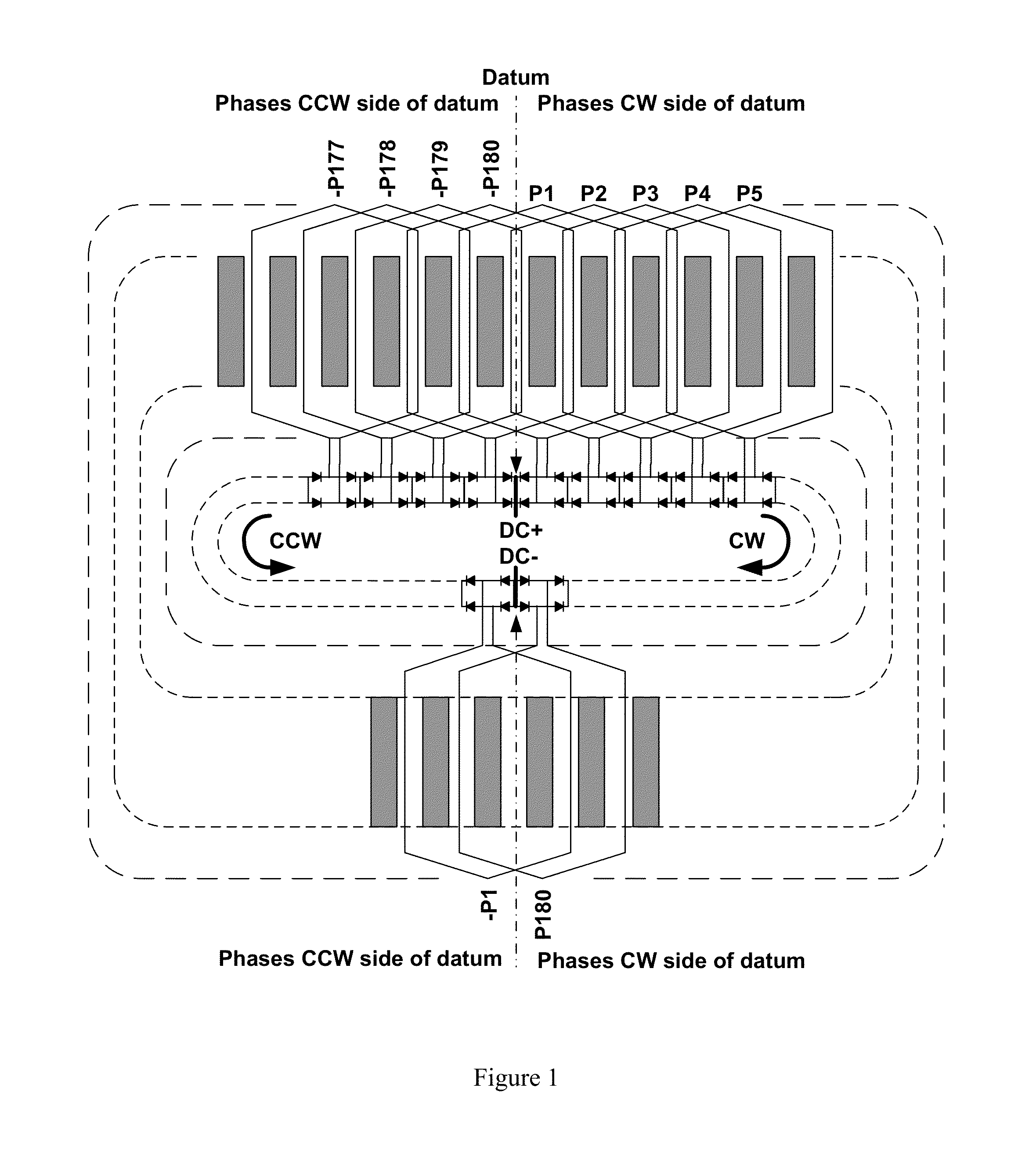
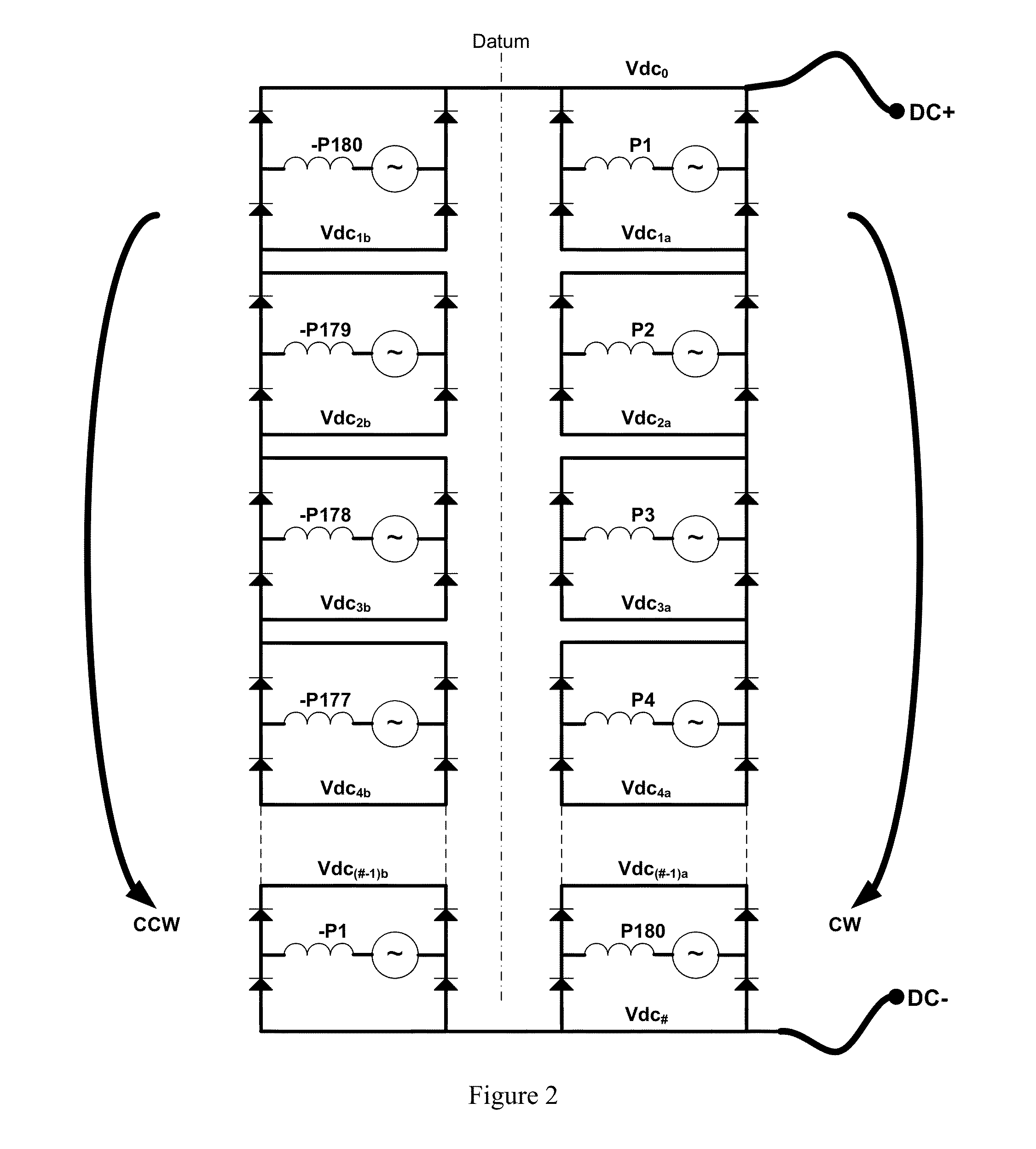
[0067]A dc electrical machine according to an embodiment of the present invention is shown schematically in FIGS. 1, 2, and 3. A dc electrical machine according to an embodiment of the present invention is shown schematically in FIGS. 4, 5, and 6. It will be readily appreciated that the rotor and much of the stator have been omitted from FIGS. 1 and 4 for clarity.

[0068]In embodiments, the stator (or armature) assembly of the electrical machine has 360 winding slots (Ns=360) for receiving the coils of the stator winding. In an embodiment, the stator winding includes 360 two-layer coils. In an embodiment, the stator winding includes 180 single-layer coils. Although not shown, the stator could have an odd number of winding slots or a tooth concentrated winding where each coil is wound around a stator tooth.

[0069]According to an embodiment, a datum is provided by the co-located local positive dc terminals Vdco of first and second segments (corresponding to first and second dc circuits) ...


PUM


Abstract

A dc electrical machine with a large number of phases. The machine includes a rotor and a stator assembly. The rotor has Np rotating field poles. The stator has Ns winding slots, where Ns/Np is a non-integer ratio. A stator winding includes a plurality of coils received in the winding slots and defines a plurality of stator phases. A power electronic switching assembly includes first and second dc load terminals that can be connected to external equipment and a plurality of switching modules. Each switching module includes power electronic devices and is connected to a respective stator coil. A first proportion of the switching modules are connected together in series between the first and second dc load terminals and a second proportion of the switching modules are connected together in series between the first and second dc load terminals to define two parallel dc circuits.

Description

FIELD OF THE INVENTION[0001]Embodiments of the present invention relate to dc electrical machines, and in particular to machines with high torque density and high power density, which are efficient and reliable, and are simple to install and commission.BACKGROUND OF THE INVENTION[0002]A dc rotating electrical machine typically includes a rotor surrounded by a wound stator. A rotor connected commutator with copper segments and stationary brushgear are used to control the commutation of current in the rotor winding based on the angular position of the rotor. Brush commutated dc electrical machines are known to be capable of high air gap shear stress but their practical torque density performance is limited by the brush commutation process. The stationary brushgear and rotating commutator converts the dc terminal voltage of the electrical machine into a polyphase ac voltage that rotates within the armature winding in a direction and at a speed that causes the armature magneto-motive fo...

Claims


Application Information

Patent Timeline
IPC IPC(8): H02K11/00
CPCH02K11/0073H02K3/28H02K11/33H02K2213/12H02P6/14H02P25/22Y02E10/72
Inventor CRANE, ALLAN
Owner GE ENERGY POWER CONVERSION TECH
Why Eureka
Try Eureka