
Systems and methods for illumination control and distribution during a vehicle bank

a vehicle bank and illumination control technology, applied in the direction of lighting and heating apparatus, cycle equipment, instruments, etc., can solve the problems of complex electronics, complex computations, and complex mechanical systems, and achieve accurate calculation and accurate calculation

Active Publication Date: 2018-07-17
J W SPEAKER CORP
View PDF79 Cites 4 Cited by
  • Summary
  • Abstract
  • Description
  • Claims
  • Application Information

AI Technical Summary

Benefits of technology

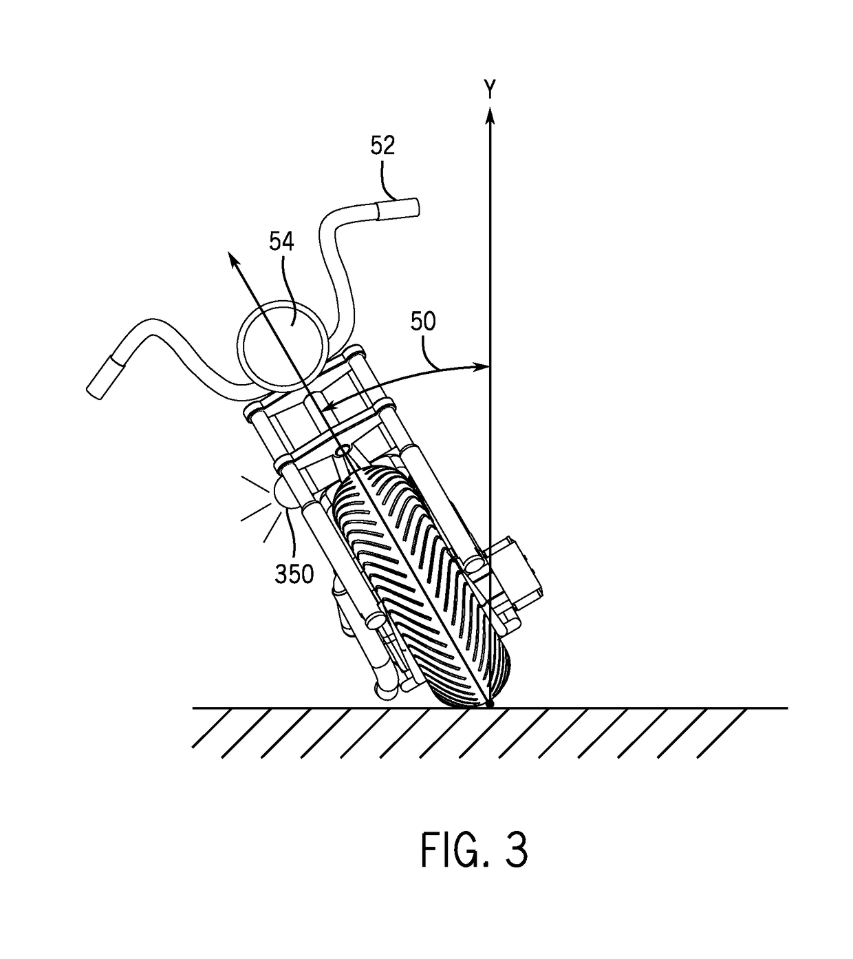
The patent text describes how to accurately calculate the angle of a vehicle and control the illumination optics to keep the illumination pattern horizontal. This is useful for maintaining a good field of view for the driver, especially when the vehicle is tilting due to a slope in the road. The illumination optics can include a primary and side groups. The main technical effect of this patent is to provide a more natural field of view for the driver during a tilting motion.

Problems solved by technology

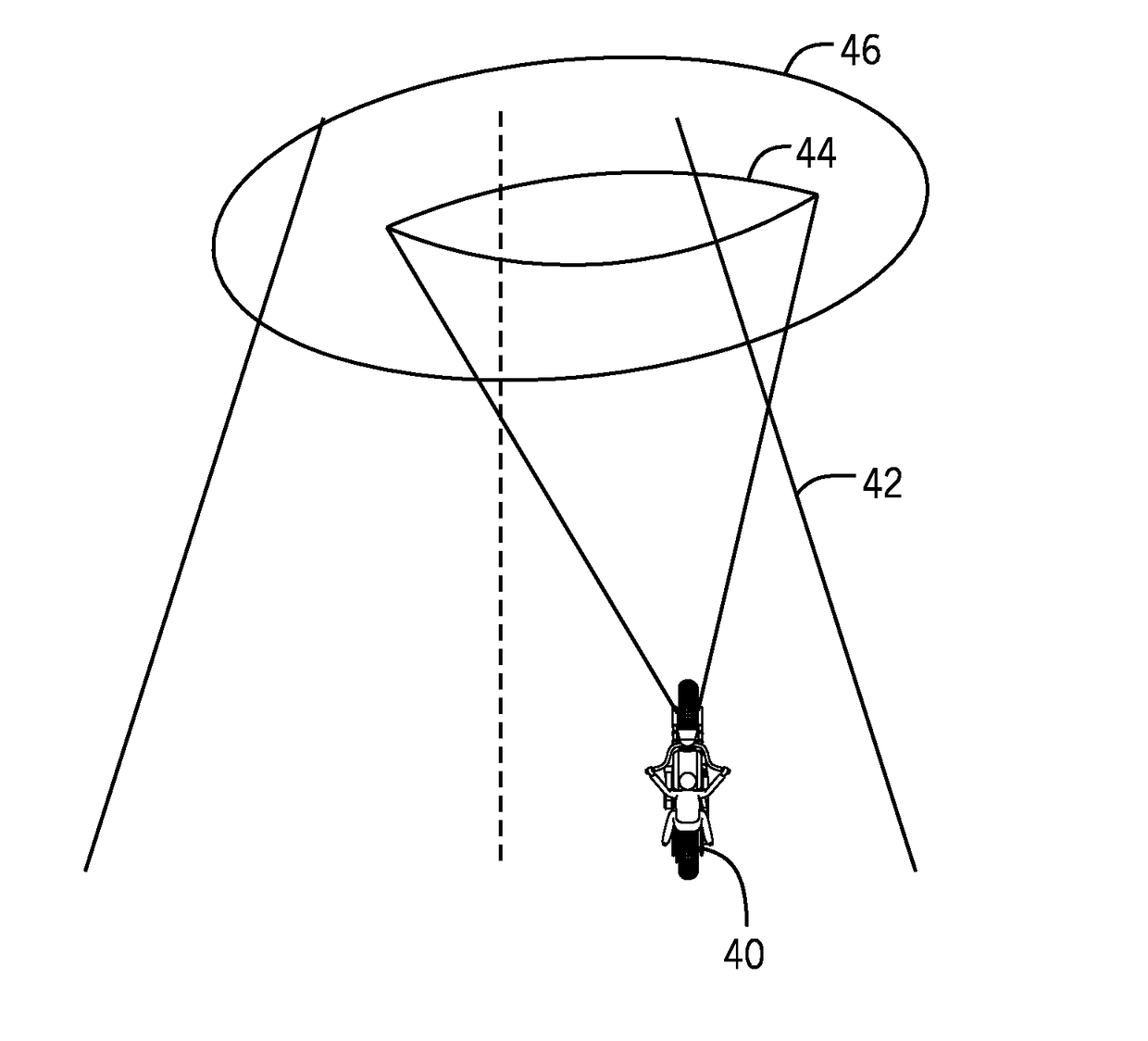
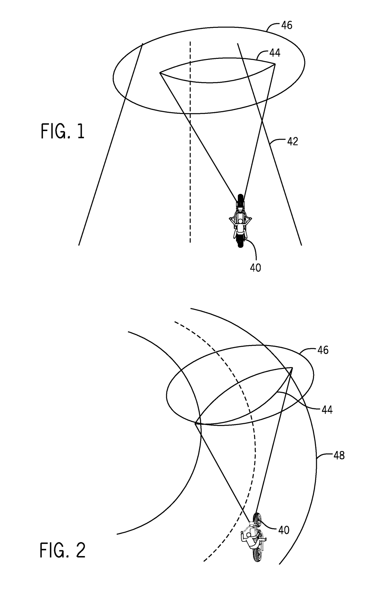
Unfortunately, the light beam pattern 44 suits illumination requirements when the motorcycle is traveling generally straight forward, but not when the motorcycle is banking.
Each of these systems requires complex computations, which require complex electronics, and they also require sophisticated mechanical systems to provide movement of the illumination from the light source.
The mechanical systems add complexity and cost to both the headlight and the overall vehicle cost.
Although this type of arrangement may provide adjustable horizontal illumination for an automobile, it inadequately addresses the effect when a vehicle, such as a motorcycle, is banking.

Method used


Image

  • Systems and methods for illumination control and distribution during a vehicle bank
  • Systems and methods for illumination control and distribution during a vehicle bank
  • Systems and methods for illumination control and distribution during a vehicle bank

Examples


Embodiment Construction

[0041]The various aspects of the subject invention are now described with reference to the annexed drawings, wherein like reference numerals correspond to similar elements throughout the several views. It should be understood, however, that the drawings and detailed description hereafter relating thereto are not intended to limit the claimed subject matter to the particular form disclosed. Rather, the intention is to cover all modifications, equivalents, and alternatives falling within the spirit and scope of the claimed subject matter.

[0042]As used herein, the terms “component,”“system,”“device” and the like are intended to refer to either hardware, a combination of hardware and software, software, or software in execution. The word “exemplary” is used herein to mean serving as an example, instance, or illustration. Any aspect or design described herein as “exemplary” is not necessarily to be construed as preferred or advantageous over other aspects or designs.

[0043]Furthermore, th...


PUM


Abstract

A bank angle of a vehicle can be accurately calculated using yaw axis data and roll axis data, and based on the calculated bank angle, vehicle illumination optics can be controlled to maintain a pattern of distributed light from the illumination optics to be generally horizontal. The calculated bank angle may be zeroed when the yaw axis data equals zero. The improved pattern of distributed light from the illumination optics illuminates a more natural field of view for the vehicle driver during a bank. In some embodiments, the vehicle illumination optics can include a primary illumination group and a plurality of side illumination groups.

Description

CROSS-REFERENCE TO RELATED APPLICATIONS[0001]This application claims the benefit of U.S. Provisional Patent Application Ser. No. 61 / 877,513, filed Sep. 13, 2013, and entitled “Systems and Methods for Illumination Control and Distribution During a Vehicle Bank,” which is herein incorporated by reference.STATEMENT REGARDING FEDERALLY SPONSORED RESEARCH OR DEVELOPMENT[0002]Not applicable.BACKGROUND OF THE INVENTION[0003]The present invention relates to systems and methods for illumination control and distribution during a vehicle bank, such as when vehicle banks in order to take a curve or to turn, and more specifically to illumination control and distribution systems and methods that control and maintain a pattern of light generally horizontal during the vehicle bank.[0004]For example, FIG. 1 shows a motorcycle 40 traveling generally straight in a lane on a road 42. As can be seen, motorcycle headlights have a primarily horizontally shaped light beam pattern 44 that is shaped accordin...

Claims


Application Information

Patent Timeline
Patent Type & Authority Patents(United States)
IPC IPC(8): B60Q1/115B62J6/02G01B5/24B60Q1/12G01C19/00B60Q1/34
CPCG01B5/24G01C19/00B62J6/02B60Q1/115B60Q1/12B60Q1/346B60Q2300/136B60Q2300/134B60Q2300/128B60Q1/0041F21S41/663F21W2102/155B62J6/023B60Q1/0023F21S41/151F21S41/153
Inventor MCWITHEY, KEVIN JAYKAY, BRADLEY WILLIAMPOPOVIC, DRAGOLSAV
Owner J W SPEAKER CORP
Learn More