One-piece sill pan flashing

a one-piece, flashing technology, applied in the direction of sills/thresholds, condensed water draining off, corners/edge joints, etc., can solve the problems of deterioration of sealing materials, deterioration of wood framing and housing structure, and extra labor time, etc., to achieve the effect of occupying

Active Publication Date: 2018-07-17
SILL DRY IND LLC
View PDF20 Cites 8 Cited by
  • Summary
  • Abstract
  • Description
  • Claims
  • Application Information

AI Technical Summary

Benefits of technology

[0009]Our present invention is an even further improvement on our earlier invention in that the construction of the flashing enables it to be either expanded or compressed in width by very substantial amounts. An extremely important benefit of this characteristic is that the new sill pan flashings can be designed to a particular nominal flashing width, with the capability of being either enlarged or compressed substantially in length. The improved flashing thus can be installed in rough framing of a range of nominal framing widths both larger and smaller than the nominal width of the flashing itself. This characteristic enables manufacturers and sellers (typically large “home improvement” stores) to stock a much smaller inventory of flashing widths in relation to the more numerous nominal sizes of window and door framing in which the flashings are to be installed. This is an important advantage inasmuch as a one-piece flashing can be relatively large and bulky and occupy a significant amount of storage space. Since one flashing size according to our invention can be applied to a plurality of window sizes, the required inventory of sizes may be reduced to a fraction of what otherwise would be required.

Problems solved by technology

Over time the sealing material may deteriorate and allow some moisture to penetrate.
This can result in deterioration of the wood framing and of housing structure below the framed opening.
This presents a problem with respect to the installation of the sill pan flashings, because the required width of the flashing, in order to fit snuggly between the vertical elements of the frame, may be different for each of many framed openings that are “nominally” of the same size.
Among others, the individual installation of the two (or more) components, and the sealing of the interface(s) between them consumes extra labor time and thus adds to the cost of construction.
Additionally, construction sites are often somewhat chaotic, and it is not uncommon for the individual components of a multi-part flashing assembly to become separated at the job site, so that all of the mating parts may not be readily available when the worker is ready to install them.
Moreover, the caulking material, which is required to seal the interface between the parts, frequently is hastily and / or carelessly applied at the job site.
If the sealant is not applied in a proper unbroken bead between the parts, the interface can become a source of water intrusion and damage.

Method used


Image

  • One-piece sill pan flashing
  • One-piece sill pan flashing
  • One-piece sill pan flashing

Examples


Embodiment Construction

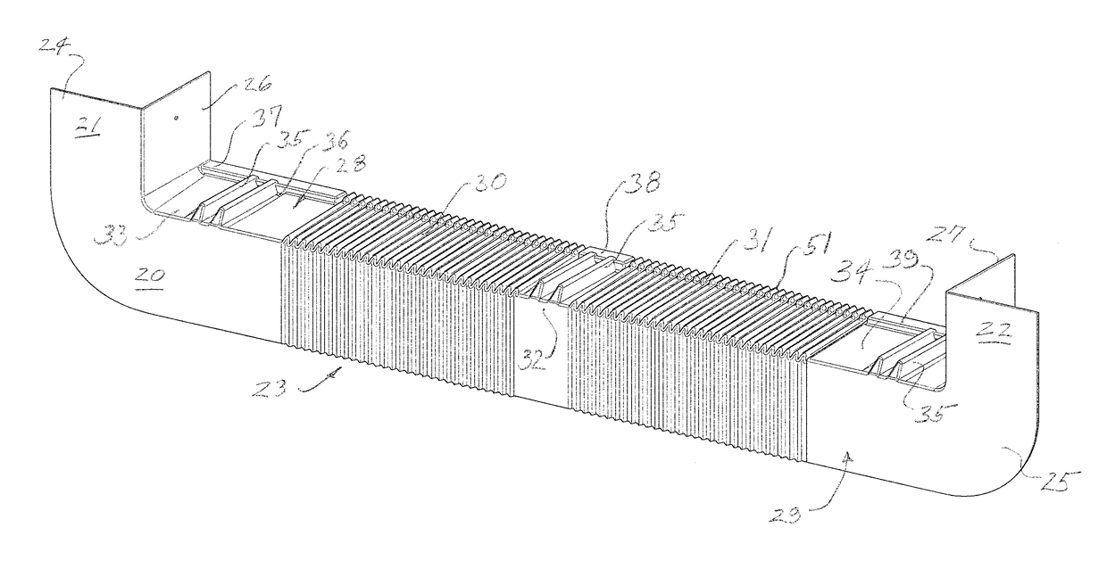
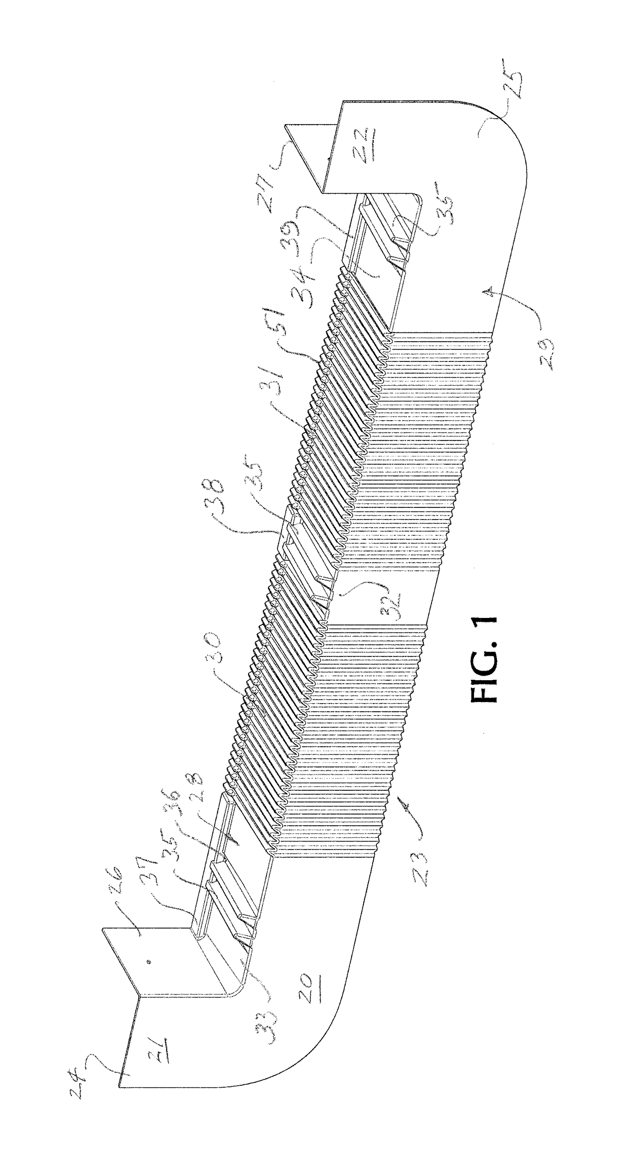
[0020]Referring now to the drawings, the numeral 20 designates a sill pan flashing according to the invention, preferably formed of a single sheet of plastic material, preferably a thermoplastic polyolefin, preferably using a thermoforming process, but alternatively also as a single injection molded part of a similar material. For a thermoforming process, it is contemplated to utilize a sheet of plastic material of, for example, about 0.080 in in thickness. The flashing 20 is comprised of flanged end portions 21, 22 at opposite sides and a sill plate cover 23 extending between and joining the spaced apart end portions. The two end portions have front-facing vertical walls 24, 25 joined along vertical edges with laterally inwardly facing vertical walls 26, 27. These walls form rigid corners which are intended to engage and be secured to outer sheathing 17 and spaced-apart upright members 18 (FIG. 5) of a rough-framed opening of a suitable size and shape (typically rectangular) for th...


PUM


Abstract

A one-piece sill pan flashing is provided with one or more accordion sections. At least the accordion sections, and preferably the entire flashings, are formed of a single sheet of thermoplastic material, preferably by thermoforming, and include forwardly and downwardly inclined upper portions and vertical lower portions extending downward from the front of the upper portions. The accordion sections include upper and lower portions, formed of narrow panels, foldably connected along their lateral edges to form V-shaped accordion folds having a series of ridge folds and valley folds. The valley folds of the upper portions are aligned with the ridge folds of the lower portions and vice versa. The construction accommodates substantial extension or compression of the width of the flashing and enables one size of flashing width to be fitted to a wide range of sizes of rough-framed window openings.

Description

FIELD OF THE INVENTION[0001]The invention relates generally to the field of home and office construction and more particularly to a novel and improved, adjustable one-piece sill pan flashing for installation at the bottom of the rough framing of a window or door opening in order to prevent penetration of water underneath a window or door sill and into the underlying framing structure.BACKGROUND OF THE INVENTION[0002]In the home construction industry, it is typical for windows and doors to be constructed as independent, prefabricated units and installed in roughly framed openings constructed in the exterior walls of the home. The exterior framing of the window and door units overlap the exterior of the housing wall around the framed openings and initially are sealed to prevent access of moisture. Over time the sealing material may deteriorate and allow some moisture to penetrate. This can result in deterioration of the wood framing and of housing structure below the framed opening. A...

Claims


Application Information

Patent Timeline
Patent Type & Authority Patents(United States)
IPC IPC(8): E06B1/62E06B3/30E06B3/96E06B7/22E06B7/14E06B1/70
CPCE06B1/702E06B1/62E06B3/9632E06B3/308E06B7/14E06B7/22E06B2001/628
Inventor GLICKMAN, JOEL I.MCMAHON, KIERAN
Owner SILL DRY IND LLC
Why Eureka
Try Eureka