
Method for generating a configuration for a control unit test system

a technology of control unit and configuration, applied in the direction of programmatic control, instruments, electric digital data processing, etc., can solve the problems of inability to capture, inability to use correct hardware components in the programmed model, and inability to accurately predict the effect of the program, so as to achieve the effect of higher process reliability

Active Publication Date: 2018-07-17
DSPACE DIGITAL SIGNAL PROCESSING & CONTROL ENG
View PDF52 Cites 10 Cited by
  • Summary
  • Abstract
  • Description
  • Claims
  • Application Information

AI Technical Summary

Benefits of technology

The present invention provides a method for configuring a control unit test system that automates the process and reduces human error. The server used in the test system can be a software item executed on a separate hardware item that does not interfere with the test. Additionally, the invention allows for the use of hardware components that may not have a processor by attaching an additional server hardware item to the component. The separate network used in the invention ensures that communication between the server and computer does not disrupt the test. These technical effects improve the reliability and efficiency of the control unit test system.

Problems solved by technology

One concrete example from the motor vehicle field is the attachment of a throttle valve to the test system, since this component exhibits a behavior that is difficult to impossible to capture in simulation.
Such a configuration, which is to say the assembling of the individual hardware components of the test system and the incorporation of such hardware components in a model to be executed, is performed largely manually, with the result that susceptibility to errors of the test system, in particular the model executed therein, also results from incorrect hardware components being used in a programmed model during configuration, or from an incorrect model, or at least an incorrectly configured or parameterized model for the given hardware components, being assembled or programmed.
For example, if a certain test, which is to say a certain environmental condition or interaction of a control unit with the simulated environment, is to be tested, an error can be caused simply by the fact that a model is used in the simulation that expects data that are not provided by the hardware components, or that processes these data in a manner that is not appropriate for the applicable hardware components.
For example, if a throttle valve controller for a 6-cylinder engine that is implemented in a control unit is to be tested by means of a test system, it is evident that this test cannot be performed correctly if configuration or parameterization of the model that is employed takes place for a 4-cylinder throttle valve.

Method used


Image

  • Method for generating a configuration for a control unit test system
  • Method for generating a configuration for a control unit test system

Examples


Embodiment Construction

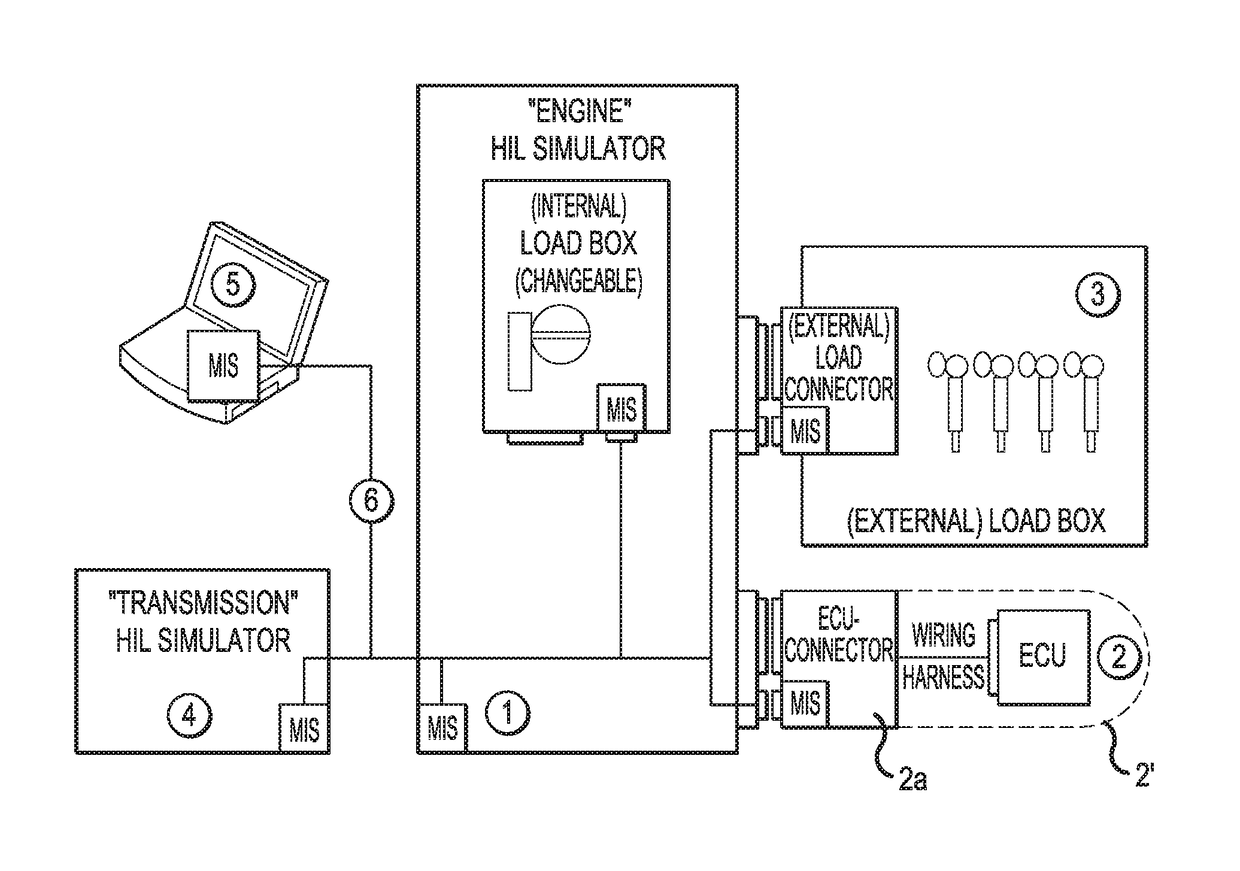
[0061]FIG. 1 shows, in an overall view in the form of a block diagram, a test system 1 for performing a test of a control unit 2, in which an environment is simulated for a control unit 2 by means of a simulation architecture, in particular an environment such as is also present in the actual use of the control unit 2 in a later device, as for example a motor vehicle.

[0062]The simulation architecture can already comprise multiple hardware components, for example a computer—not shown here—of the test system 1 and can be implemented, for instance, through a proprietary system of a particular manufacturer. In the present case, a system of the patent applicant is shown in which multiple hardware components 2, 3, 4 can communicate with one another over a network 6; these components are connected to the test system 1, upon which the computer, not shown, simulates a test environment.

[0063]Here, the hardware components 2, 3, 4 can be incorporated in the network 6, e.g. through intelligent n...


PUM


Abstract

A method for performing configuration of a control unit test system with hardware components connected thereto, wherein control units can be tested with the test system in an environment simulated by the test system by means of a model, and wherein the test system comprises at least one computer, in particular a computer executing the model, as well as hardware components, connected to one another by means of at least one network, in which at least a portion of the hardware components comprises a dedicated server (MIS) that, by means of communication, provides access to the configuration data associated with the hardware component, in particular stored in the hardware component, and the model and / or the hardware component is adapted, in particular configured, as a function of the configuration data that are made accessible.

Description

[0001]This nonprovisionalq application claims priority under 35 U.S.C. § 119(a) to European Patent Application No. EP 13156323.1, which was filed on Feb. 22, 2013, and which is herein incorporated by reference.BACKGROUND OF THE INVENTION[0002]Field of the Invention[0003]The present invention relates to a method for generating a configuration for a control unit test system with hardware components connected thereto, wherein control units can be tested with the test system in an environment simulated by the test system by means of a model, and wherein the test system comprises at least one computer, in particular a computer executing the model, as well as hardware components, that are connected to one another by means of at least one network.[0004]Description of the Background Art[0005]Test systems for performing control unit tests are known in the prior art. For example, control units for motor vehicles can be tested, as well as control units for other devices such as, e.g., automate...

Claims


Application Information

Patent Timeline
Patent Type & Authority Patents(United States)
IPC IPC(8): G06F17/50G05B23/02
CPCG06F17/50G05B23/0208G05B23/0213Y02T10/82G05B2219/23446G06F30/00
Inventor PAULE, JUERGENKLAHOLD, JUERGEN
Owner DSPACE DIGITAL SIGNAL PROCESSING & CONTROL ENG
Learn More