
Method of reducing random drift in the combined signal of an array of inertial sensors

a combined signal and inertial sensor technology, applied in the field of sensors and inertial measurement units, can solve the problems of time-consuming and processor-intensive prior art methods, and achieve the effect of optimal linear combination of signals

Active Publication Date: 2018-07-17
UNITED STATES OF AMERICA
View PDF4 Cites 8 Cited by
  • Summary
  • Abstract
  • Description
  • Claims
  • Application Information

AI Technical Summary

Benefits of technology

The present invention provides a method to estimate the correlations between drift components of different sensors from a finite amount of calibration data. Also, it derives an optimal coefficient vector to weight the output signal vector of an array of inertial sensors, such as gyroscopes, to create an optimal linear combination of signals.

Problems solved by technology

These prior art methods tend to be time consuming and processor intensive.
Among the dominant noise sources, the additive noise terms for different sensors are uncorrelated, however, there may be correlations between the random drift of different sensors.

Method used


Image

  • Method of reducing random drift in the combined signal of an array of inertial sensors
  • Method of reducing random drift in the combined signal of an array of inertial sensors
  • Method of reducing random drift in the combined signal of an array of inertial sensors

Examples


Embodiment Construction

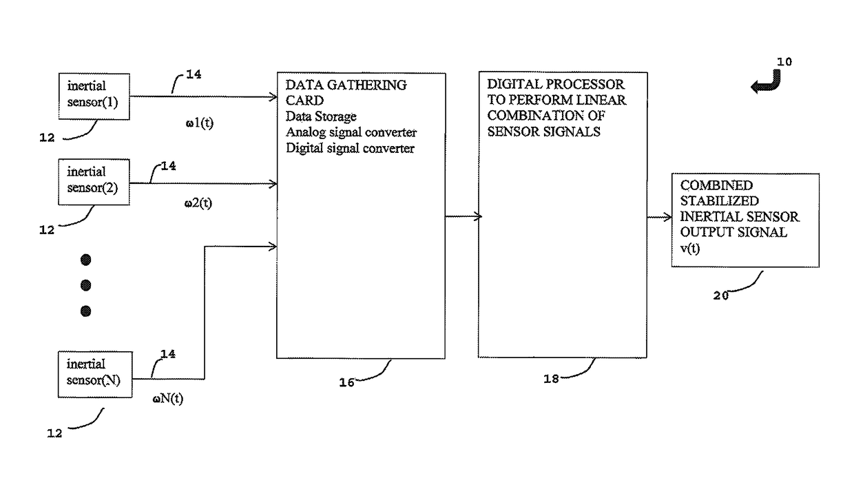
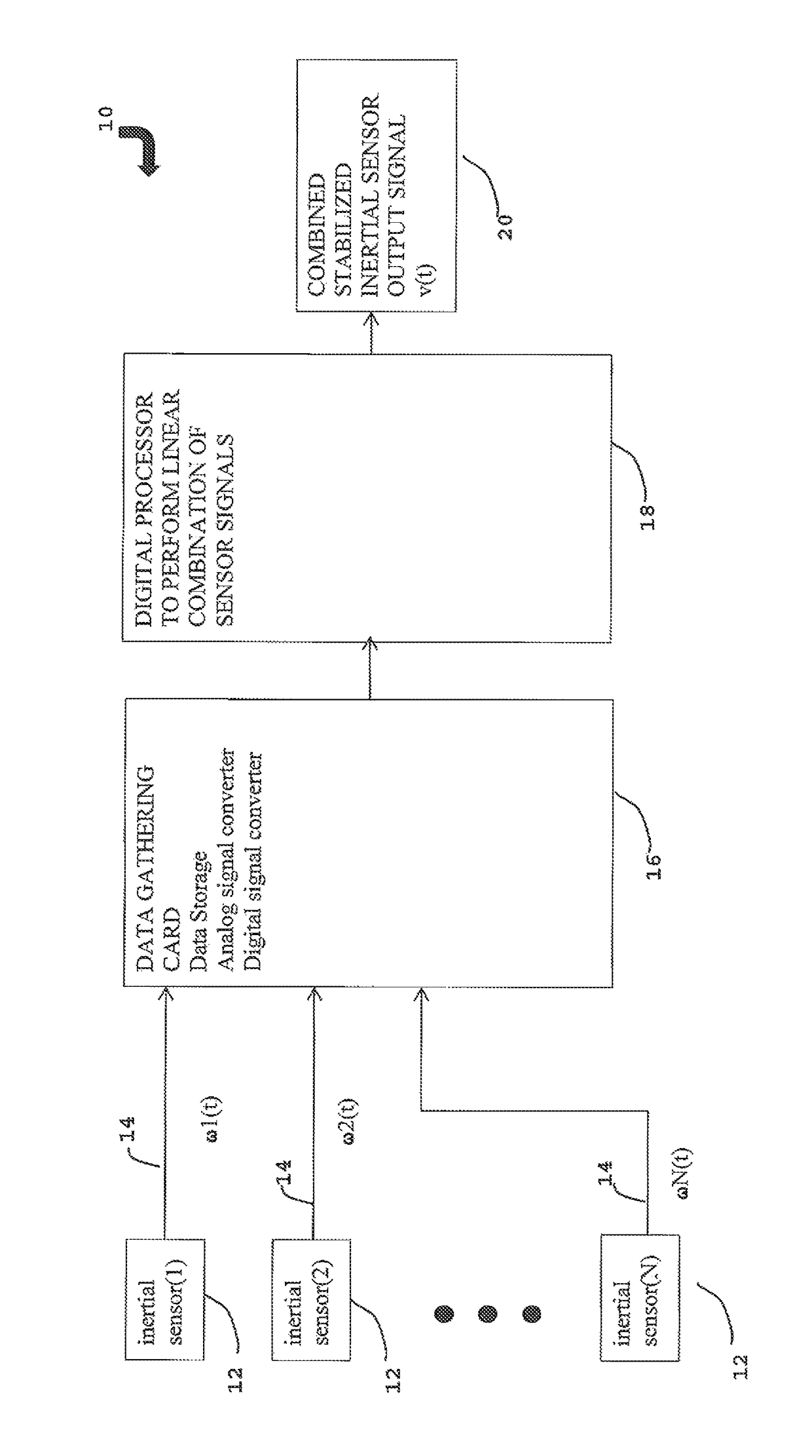
[0012]The present invention is a method of combining multiple sensor outputs from an array of inertial sensors. Referring to FIG. 1 there is illustrated an inertial measurement unit 10 that consists of the following components: an array of N inertial sensors 12, an electronic data gathering card 16 joined to the array of N inertial sensors 12, and an electronic digital processor 18 joined to the data gathering card 16. In a preferred embodiment the inertial sensors 12 are tactical-grade microelectromechanical systems (MEMS) 3 axes orthogonal accelerometers or 3 axes orthogonal gyroscopes. Each inertial sensor 12 in the array generates a signal 14 that is received by the data gathering card 16. In a preferred embodiment, the data gathering card 16 will have data storage capability and be capable of performing analog to digital conversion or digital to analog conversion depending upon the type of inertial sensor 12 used. The digital processor 18 can be a microcontroller and will be pr...


PUM


Abstract

The disclosed invention provides a method that exploits the correlations in the statistical properties of one inertial sensor to another. Among the dominant noise sources, the additive noise terms for different sensors are uncorrelated, however, there may be correlations between the random drift of different sensors. The method of the present invention estimates these correlations from a finite amount of calibration data in order to calculate coefficients for the optimal linear combination of multiple sensor signals. The method is a means of combining the multiple sensor outputs to obtain a virtual sensor signal with reduced drift, and in a far more time efficient and less processor intensive way than the prior art.

Description

STATEMENT OF GOVERNMENT INTEREST[0001]The invention described herein may be manufactured and used by or for the Government of the United States of America for governmental purposes without the payment of any royalties thereon or therefore.CROSS REFERENCE TO OTHER PATENT APPLICATIONS[0002]None.BACKGROUND OF THE INVENTION(1) Field of the Invention[0003]The present invention relates to the components of inertial measurement units, sensors such as gyroscopes and accelerometers. More particularly, the invention relates to a method to calculate optimal weights for use in combining the signals from an array of gyroscopes or accelerometers into a single, low-drift signal to improve the resonant sensor bias stability relative to a single gyroscope or accelerometer.(2) Description of the Prior Art[0004]Gyroscopes and accelerometers are necessary components of inertial measurement units (IMUs), which are used for the guidance and stabilization of many platforms. The performance of a rate gyros...

Claims


Application Information

Patent Timeline
IPC IPC(8): G01C19/00G06F17/50G01P21/00G01C25/00G06F17/18G06F17/16
CPCG06F17/5009G01P21/00G01C25/00G06F17/18G06F17/16G01C25/005G01C21/166
Inventor ZAKI, AHMED SVACCARO, RICHARD
Owner UNITED STATES OF AMERICA
Learn More