Method of obtaining micrographs of transparent or semi-transparent specimens using anisotropic contrast

a micrograph and contrast technology, applied in the field of non-destructive methods for producing magnified images of samples, can solve the problems of limited design of such materials, inability to provide images of cells' interactions with local microenvironments, and destructive current imaging techniques

Active Publication Date: 2018-07-17
J A WOOLLAM CO +1
View PDF4 Cites 6 Cited by
  • Summary
  • Abstract
  • Description
  • Claims
  • Application Information

AI Technical Summary

Benefits of technology

[0022]Said method can provide that the system capability that enables varying the sample magnification is achieved by varying the beam path configuration.

Problems solved by technology

However, the design of such materials is limited due to a lack of mechanistic understanding of how biomolecules interact with nanostructured substrates.
Further, current approaches to imaging techniques are often destructive, in that cells must be modified by means of cell fixing and labeling, to obtain images of specific cell organelles, proteins or nucleic acids.
Furthermore, currently available imaging modalities are not able to provide images of cells' interactions with their local microenvironment, such as infiltrations with two and three dimensional substrates.

Method used


Image

  • Method of obtaining micrographs of transparent or semi-transparent specimens using anisotropic contrast
  • Method of obtaining micrographs of transparent or semi-transparent specimens using anisotropic contrast
  • Method of obtaining micrographs of transparent or semi-transparent specimens using anisotropic contrast

Examples


Embodiment Construction

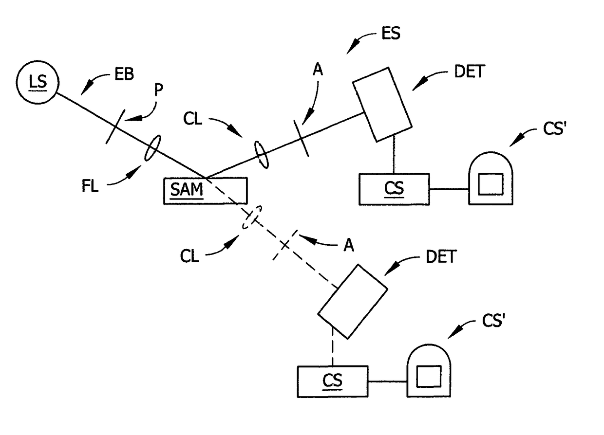
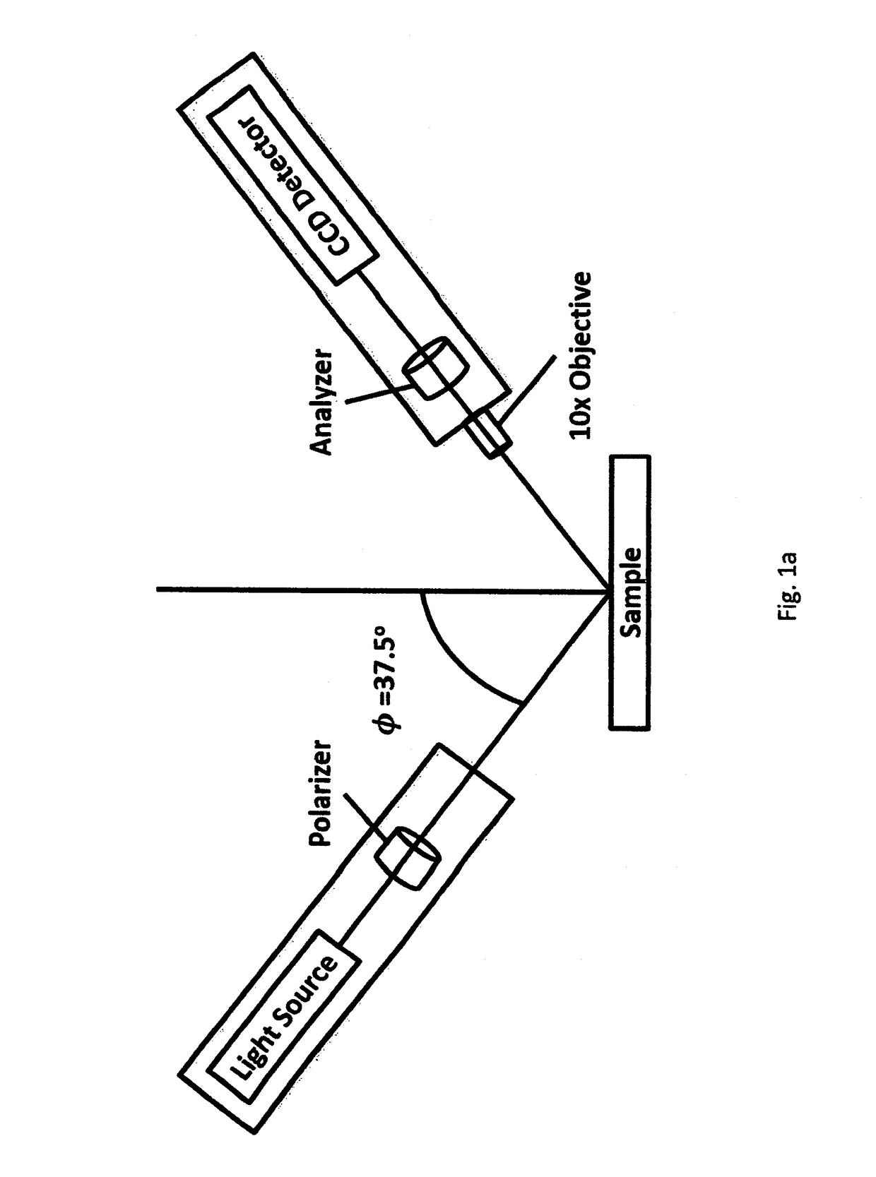
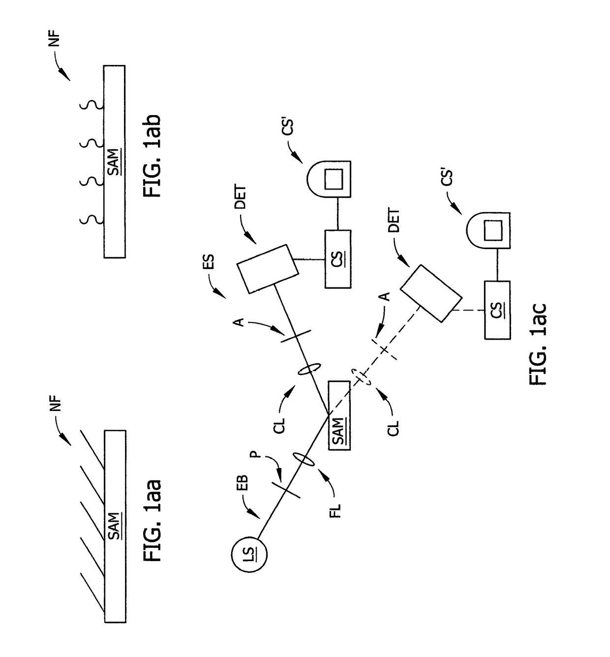
[0093]In contrast to traditional microscopy techniques where cells are commonly imaged on flat substrates, Mueller Matrix Birefringent Microscopy (MMBM) utilizes nanostructured, optically birefringent surfaces, which enhances image construction via substrate anisotropy, and this uniquely situates the present invention technique for the study of protein and cellular interactions on nanoscale features. In the present invention, birefringent substrates were fabricated by depositing titanium (Ti) Spatially Coherent Thin Films (SCTFs) onto reflexive silicon (Si) substrates. SCTFs are fabricated by Glancing Angle Vapor Deposition (GLAD) performed with oblique angle particle flux relative to the substrate, facilitated by electron beam evaporation. This approach results in highly ordered, highly coherent and controllable architectures ranging in size and shape from nano to micro scales, depending on the vapor flux angle and deposition time length. SCTFs provide enlarged surface areas, and e...


PUM

PropertyMeasurementUnit
thicknessaaaaaaaaaa
thicknessaaaaaaaaaa
angle of incidenceaaaaaaaaaa

Abstract

Anisotropic contrast methodology in combination with use of sample investigating polarized electromagnetic radiation to provide Jones or Mueller Matrix imaging data corresponding to areas on samples.

Description

[0001]This Application Claims benefit of Provisional Application Ser. No. 62 / 124,195 Filed Dec. 11, 2014.TECHNICAL FIELD[0002]The present invention relates to non-destructive methods for producing magnified images of samples, and more particularly to methodology that does not require fluorescent labeling or lapping and staining or contrast media or fixing procedures of any kind, but instead applies an anisotropic contrast technique in combination with use of sample investigating polarized electromagnetic radiation to provide Jones or Mueller Matrix imaging data corresponding to areas on samples.BACKGROUND[0003]Nanostructured topologies have the potential to endow biomedical materials with functions that can direct cell behaviors and facilitate biomolecule retention and release. However, the design of such materials is limited due to a lack of mechanistic understanding of how biomolecules interact with nanostructured substrates. Further, current approaches to imaging techniques are o...

Claims


Application Information

Patent Timeline
Patent Type & Authority Patents(United States)
IPC IPC(8): G06T7/00G06K9/46G01J4/04G01J4/00G01N21/23G01N21/21
CPCG06T7/0012G06K9/46G01J4/04G01N21/21G01N21/23G01J4/00G06T2207/30024G06T2207/10056G06T2207/10012G01J2004/001G01N21/19G01N21/211
Inventor HOFMANN, TINOSCHUBERT, MATHIAS M.KASPUTIS, TADASPANNIER, ANGELA K.HERZINGER, CRAIG M.WOOLLAM, JOHN A.
Owner J A WOOLLAM CO
Why Eureka
Try Eureka