System for passive heat removal from the pressurized water reactor through the steam generator

a technology of steam generator and pressurized water reactor, which is applied in the direction of steam generation using hot heat carriers, greenhouse gas reduction, nuclear elements, etc., can solve the problems of insufficient heat removal from the system, achieve the effect of improving the energy efficiency and performance of heat exchangers, reducing the non-uniformity of coolant flow distribution, and reducing the number of units

Active Publication Date: 2018-07-24
SCI RES & DESIGN INST FOR ENERGY TECH ATOMPROEKT JSC ATOMPROEKT
View PDF4 Cites 0 Cited by
  • Summary
  • Abstract
  • Description
  • Claims
  • Application Information

AI Technical Summary

Benefits of technology

[0010]The technical result of the invention is increase of heat removal efficiency, flow stability in the circuit and, consequently, system operation reliability.
[0025]Experiments show that the above said system parameter correlations provide the most efficient heat removal from the steam generator owing to the optimized design of the inlet pipeline and the outlet pipeline of the system, individual coolant supply to and removal from the heat exchanger sections, optimally minimized correlation between the half-section length and heat exchanger header bore, and the best relative positioning of the heat exchanger tubes.
[0026]The correlation of the half-section length and bore of the heat exchanger headers is selected so as to minimize the non-uniformity of coolant flow distribution among the heat exchanger tubes, i.e. to reduce the so-called “header effect”. The uniform distribution of flow in the tubing is one of the main conditions for improved energy efficiency and performance of heat exchangers. One of the methods used to improve coolant distribution among the header heat exchanger channels is pressure loss reduction of the medium flow in the header. This is achieved by reducing the header length and increasing its bore within the device manufacturing process capabilities and other design features. For headers meeting the L / D≤20 criterion, pressure loss along the header length is minimal, and distribution of coolant flows among the heat exchanger tubes is the most uniform. When the said criterion is exceeded, the uniformity of medium distribution among the heat exchanger channels degrades, which results in the coolant mass flow instability and, subsequently, reduced heat output of the heat exchanger.

Problems solved by technology

However, the said designs do not provide adequate heat removal from the system.

Method used


Image

  • System for passive heat removal from the pressurized water reactor through the steam generator
  • System for passive heat removal from the pressurized water reactor through the steam generator
  • System for passive heat removal from the pressurized water reactor through the steam generator

Examples


Embodiment Construction

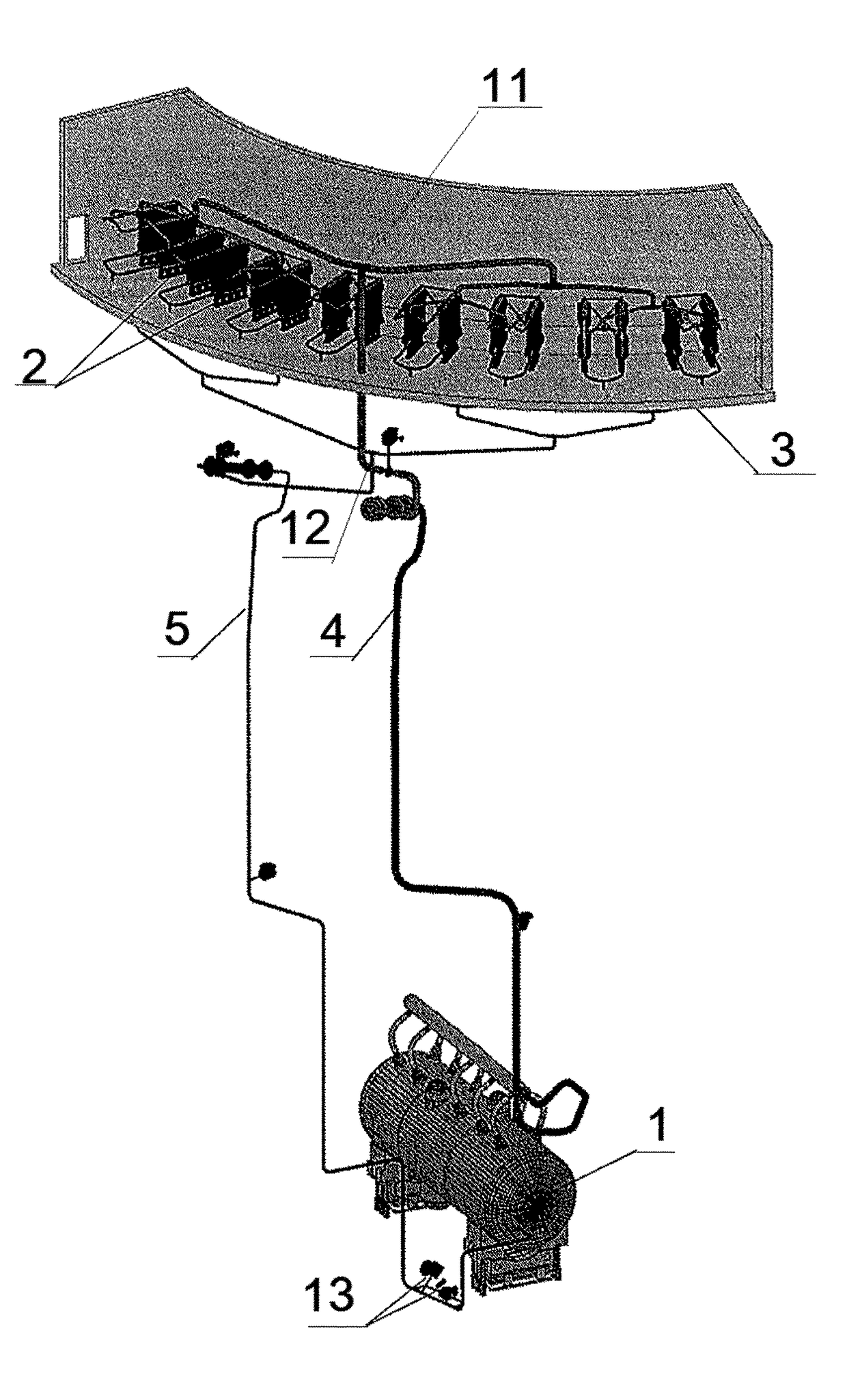
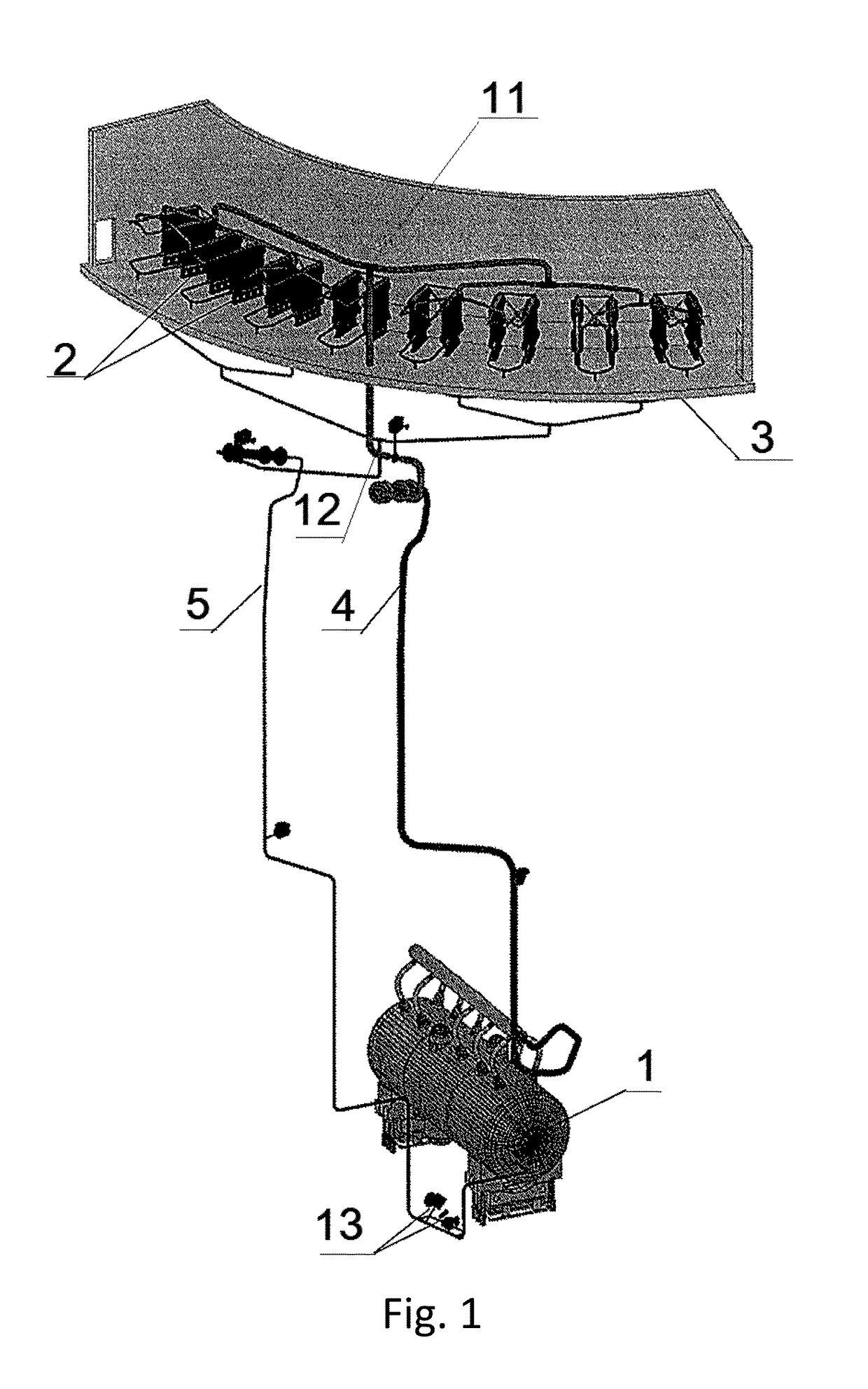
[0033]The claimed system is a combination of coolant (water) circulation circuits. In the preferable embodiment of the invention, the claimed system consists of four completely independent channels, each comprising one such circulation circuit.

[0034]The circulation circuit (FIG. 1) comprises a steam generator (1) and a sectional heat exchanger (2) located above the steam generator (1) inside a cooling water supply tank (3). The sections of the heat exchanger (2) are connected to the steam generator (1) by means of an inlet pipeline (4) and an outlet pipeline (5) so that the internal volume of the heat exchanger (2) is connected to the steam volume of the steam generator (1), i.e. the system circulation circuit is closed on its internal volume.

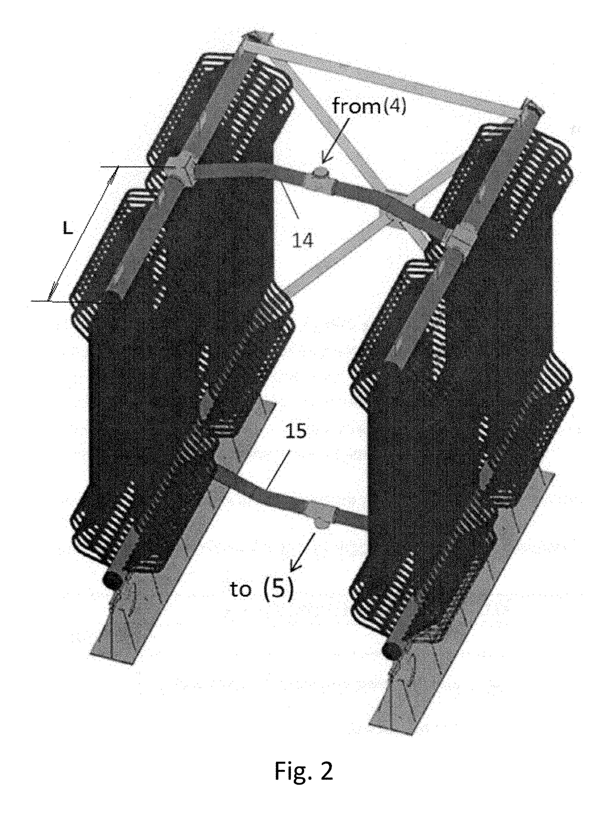
[0035]The heat exchanger is divided into sixteen parallel heat-exchange sections, each comprising two half-sections (sec FIG. 2, 3). The relation between the half-section length (L) and header bore (D) in the section shall meet the following cr...


PUM


Abstract

The invention relates to the nuclear energy field, including systems for passive heat removal from the pressurized water reactor through the steam generator. The invention increases heat removal efficiency, coolant flow stability and system reliability. The system includes at least one coolant circulation circuit comprising a steam generator and a section heat exchanger above the steam generator in the cooling water supply tank and connected to the steam generator through the inlet and outlet pipelines. The heat exchanger is divided into parallel sections wherein L / D≤20, L being the half-section length, D being the header bore, and includes an upper and lower header interconnected by heat-exchange tubes, startup valves with different nominal bores are installed on the outlet pipeline. The inlet and outlet pipeline sections of the circulation circuit comprise a set of branched parallel pipelines individually connected to each of the above heat exchanger sections.

Description

CROSS-REFERENCE TO RELATED APPLICATIONS[0001]The current application is a US 371 National Stage application from PCT / RU2015 / 000780 filed Nov. 16, 2015, which claims the benefit of priority application RU2014148909 filed Dec. 4, 2014, the disclosures of which are incorporated herein by reference in their entirety.BACKGROUND OF THE INVENTIONTechnical Field[0002]The invention relates generally to the nuclear energy field, and more particularly to systems for passive heat removal from the pressurized water reactor through the steam generator (SG PHRS), and is designed for reactor cooling by natural circulation of the coolant (water) in the system circuit.Description of Related Art[0003]According to the background of the invention, there exist numerous similar solutions disclosing different configurations of passive heat removal systems.[0004]Russian Utility Model Patent RU78600, G21C15 / 18 dated Nov. 27, 2008 discloses an emergency heat removal system comprising a steam line and a water ...

Claims


Application Information

Patent Timeline
Patent Type & Authority Patents(United States)
IPC IPC(8): G21C15/18F22B1/02
CPCF22B1/023F22B1/08G21C1/02G21C15/18F28D1/0206F28F9/26F28D1/047F28D1/05316F28D2021/0054Y02E30/30
Inventor BEZLEPKIN, VLADIMIR VICTOROVICHSIDOROV, VALDIMIR GRIGORIEVICHALEKSEEV, SERGEY BORISOVICHSVETLOV, SERGEY VICTOROVICHKUKHTEVICH, VLADIMIR OLEGOVICHSEMASHKO, SERGEY EVGENIVICHVARDANIDZE, TEYMURAZ GEORGIEVICHIVKOV, IGOR MIHAYLOVICH
Owner SCI RES & DESIGN INST FOR ENERGY TECH ATOMPROEKT JSC ATOMPROEKT
Why Eureka
Try Eureka