
Transmitter, signal synthesis circuit, and signal synthesis method
a signal synthesis circuit and signal synthesis technology, applied in the field of transmitters, signalsynthesizing circuits, signalsynthesizing methods, can solve the problems of large loss of variable inductance, large size of signal-synthesizing circuits, and difficulty in achieving a downsized signal-synthesizing circuit compatible with a plurality of transmission frequencies, etc., to achieve the effect of maintaining impedance characteristics and not increasing circuit siz
Patent Information
- Authority / Receiving Office
- US · United States
- Patent Type
- Patents(United States)
- Current Assignee / Owner
- Publication Date
- 2018-08-07
Smart Images
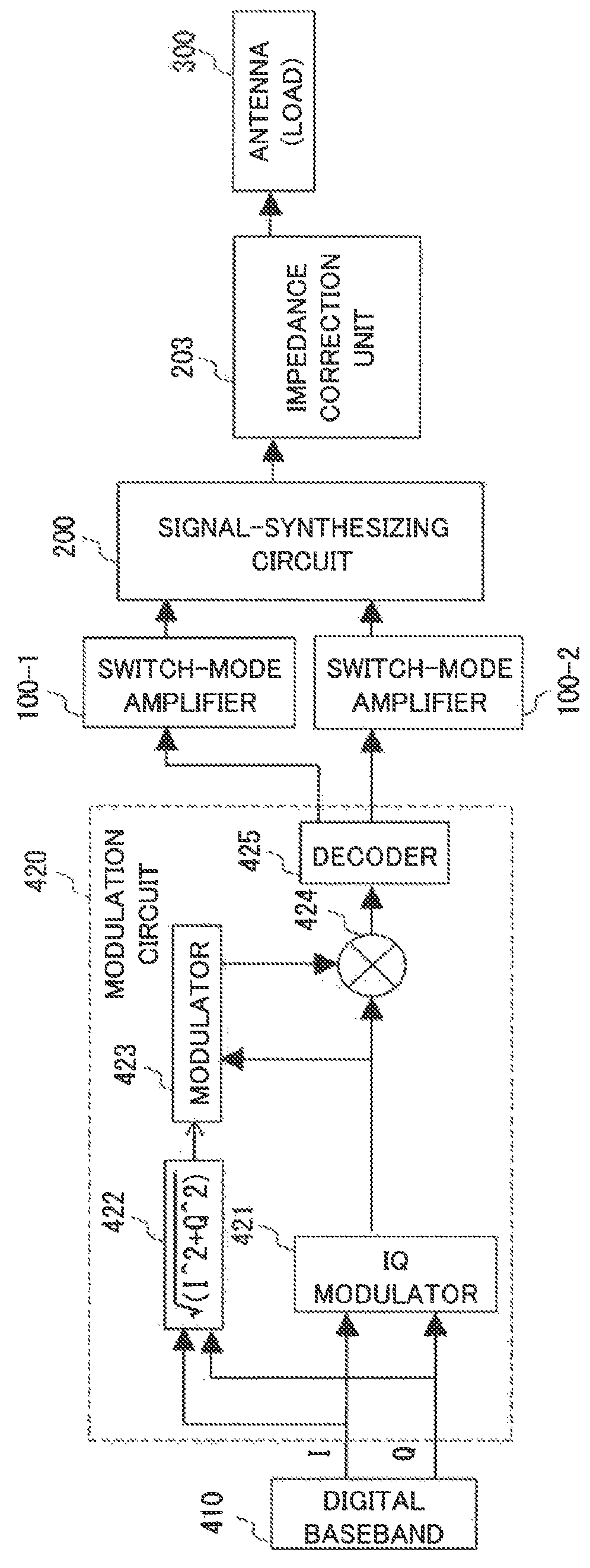
Figure 1 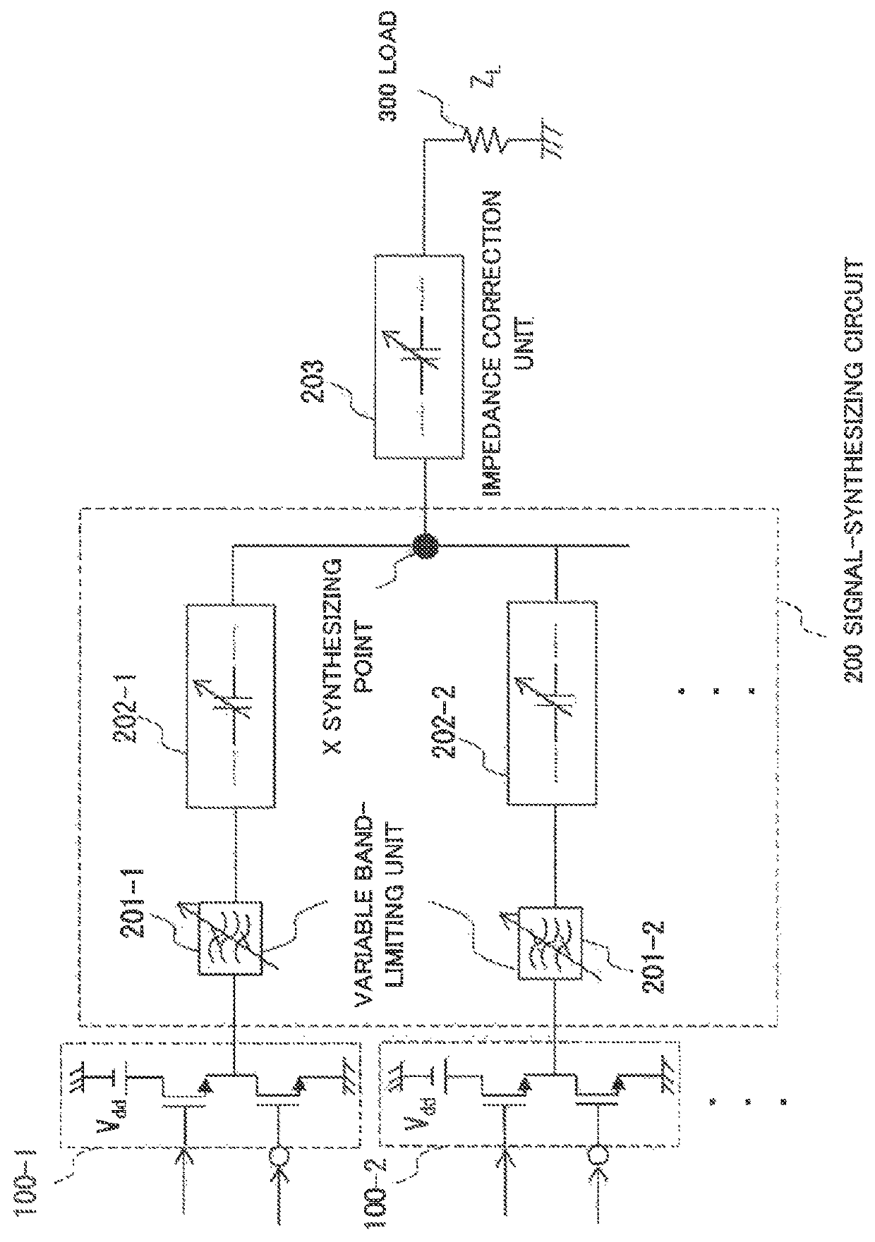
Figure 2 
Figure 3
Abstract
Description
CROSS-REFERENCE TO RELATED APPLICATIONS
[0001] This application is a national stage application of International Application No. PCT / JP2015 / 003833 entitled “TRANSMITTER, SIGNAL SYNTHESIS CIRCUIT, AND SIGNAL SYNTHESIS METHOD,” filed on Jul. 30, 2015, which claims the benefit of the priority of Japanese Patent Application No. 2014-234630 filed on Nov. 19, 2014, the disclosures of each of which are hereby incorporated by reference in their entirety.TECHNICAL FIELD
[0002] The present invention relates to a transmitter, a signal-synthesizing circuit, and a signal-synthesizing method, and more particularly, to a transmitter, a signal-synthesizing circuit, and a signal-synthesizing method that are capable of synthesizing signals of a plurality of radio frequencies. The present invention can be suitably applied as, for example, a transmitter that synthesizes output signals obtained by amplifying a multi-bit digital signal including a radio frequency band component by a plurality of switch-mode ...
Examples
example embodiments
Configuration Example of Example Embodiments
[0062]A configuration example of a transmitter according to an example embodiment of the present invention will be described in detail with reference to FIG. 1. FIG. 1 is a block diagram illustrating an example of the overall configuration of the transmitter according to an example embodiment of the present invention. As illustrated in FIG. 1, the transmitter according to the present example embodiment includes at least a digital baseband (DBB; hereinafter abbreviated as DBB) signal generation unit 410, a modulation circuit 420, switch-mode amplifiers 100-1 and 100-2, a signal-synthesizing circuit 200, an impedance correction unit 203, and an antenna (load) 300. Note that the present example embodiment illustrates a case where the impedance correction unit 203 is disposed at a subsequent stage of the signal-synthesizing circuit 200 separately from the signal-synthesizing circuit 200. However, in some cases, the impedance correction unit 20...