
Tire manufacturing system

a technology of manufacturing system and tire, which is applied in the field of tire manufacturing system, can solve the problems of large installation obstacles, large space occupation, and inability of vulcanization process to keep up with the production of green tires, and achieve the effects of reducing the space occupation of the material storage zone, and reducing the size of the member assembly devi

Active Publication Date: 2018-08-14
SUMITOMO RUBBER IND LTD
View PDF22 Cites 0 Cited by
  • Summary
  • Abstract
  • Description
  • Claims
  • Application Information

AI Technical Summary

Benefits of technology

The present invention is a tire manufacturing system that allows for the simultaneous formation of tires of different sizes on one line, reducing the number of green tires that need to be vulcanized. The system includes a track with multiple workstations, where the tire structures are formed. A member assembly device is located at each workstation and attaches the tire components to a rigid core. The system has a reduced need for pre-formed tire components and can use one member assembly device for multiple tire sizes. The track design minimizes the space needed for the system. Overall, the system allows for the downsizing of the tire manufacturing plant and the simultaneous production of tires of different sizes.

Problems solved by technology

This results in expansion of space for the material storage zone.
Since green tires of one size are mass-produced, the vulcanization process cannot keep up with the green tire production.
As a result, when a tire manufacturing plant is to be installed, the site space for the plant needs to be at least 25 m wide and 170 m long or more, which becomes a large hindrance for installation of the plant.

Method used


Image

  • Tire manufacturing system
  • Tire manufacturing system
  • Tire manufacturing system

Examples


Embodiment Construction

[0042]Embodiment of the present invention will be described below in detail.

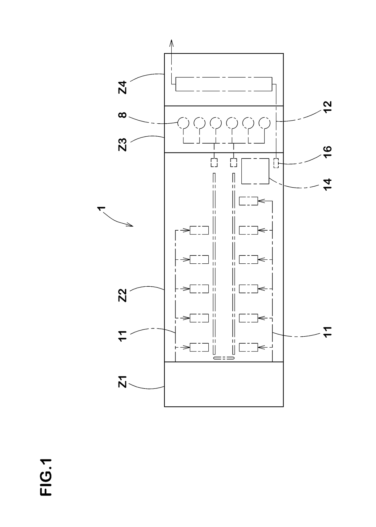
[0043]As shown in FIG. 1, a tire manufacturing system 1 according to the embodiment includes a green tire formation zone Z2 for forming a green tire 6 (shown in FIG. 5), a vulcanization zone Z3 for vulcanizing the green tire 6, an inspection and discharge zone Z4 for inspecting and discharging the vulcanized tire, and a material storage zone Z1 for storing materials for green tires.

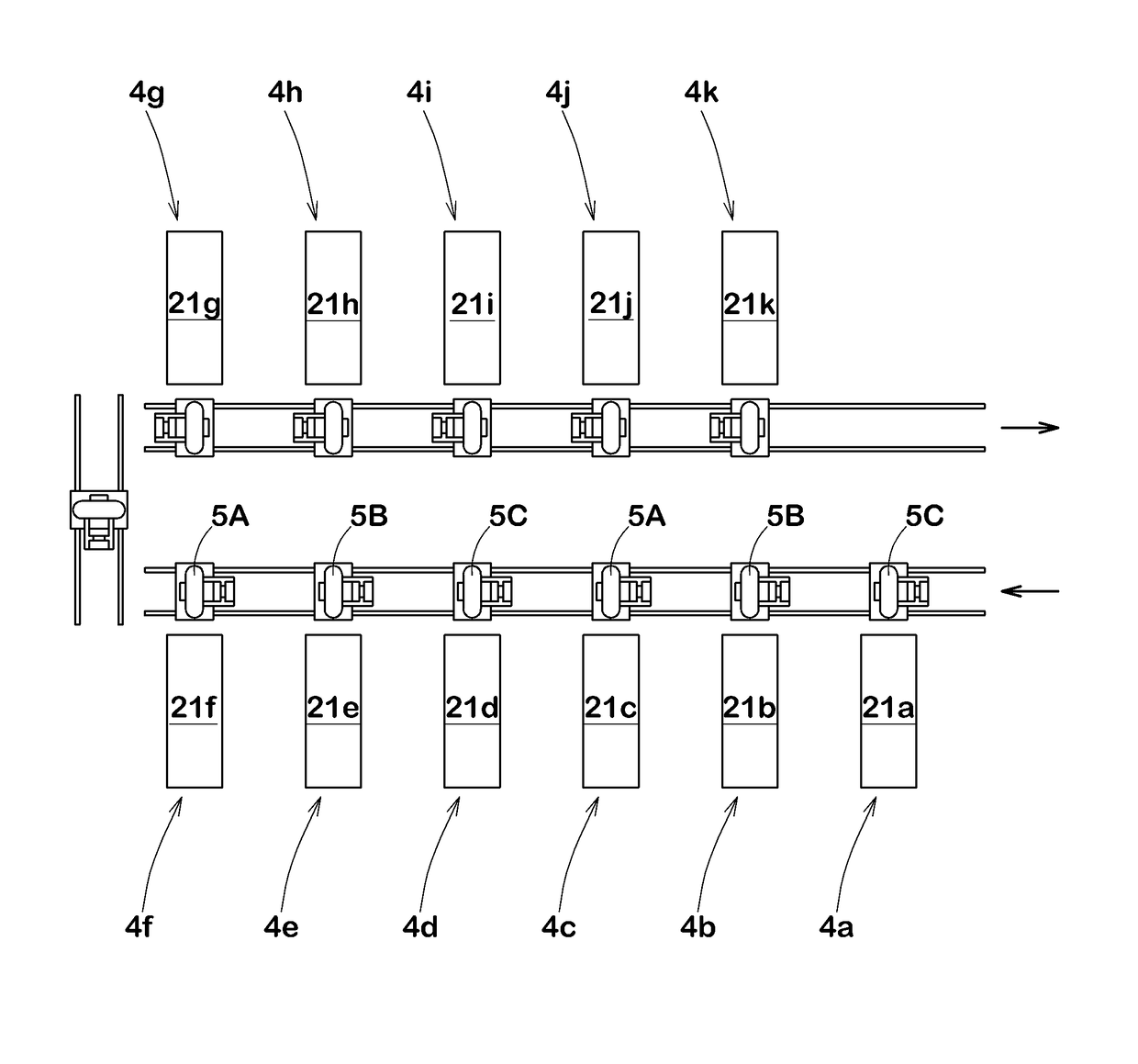
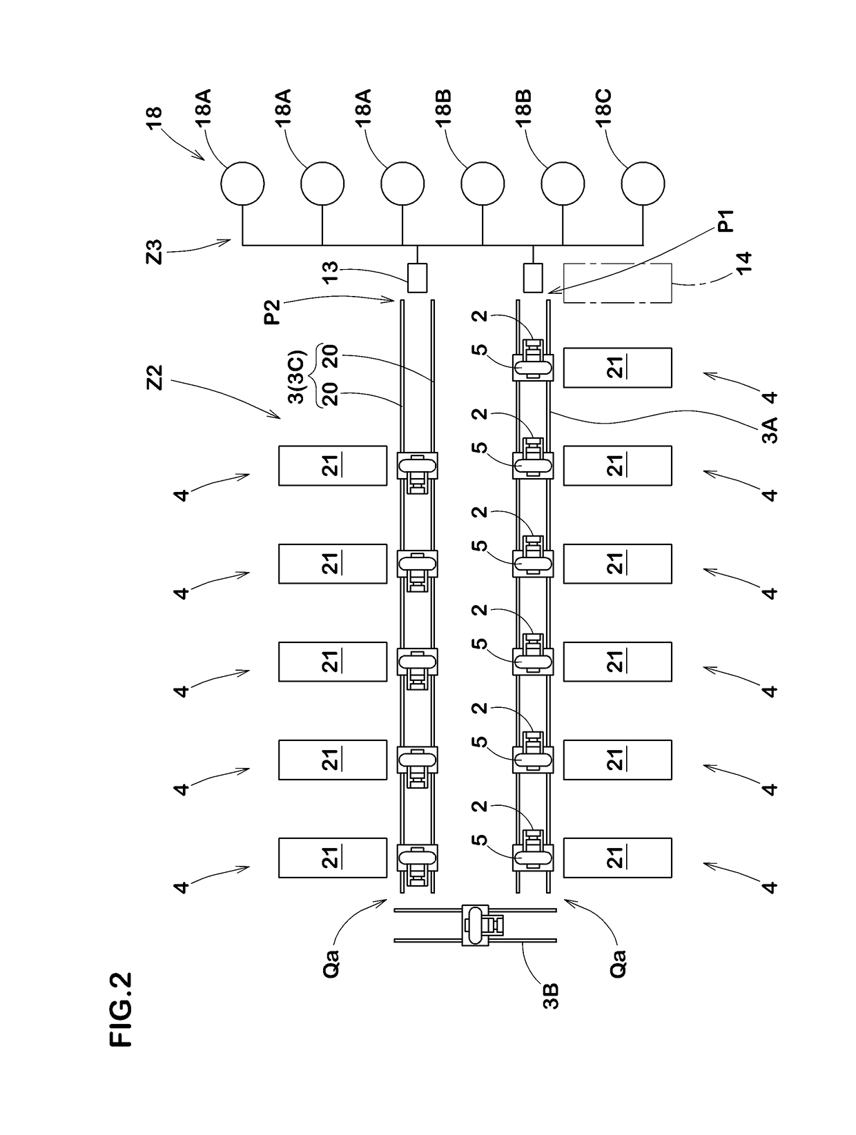
[0044]As shown in FIG. 2, among the foregoing zones, the green tire formation zone Z2 includes a green tire formation line having a track 3 and a plurality (n) of work stations 4 arranged along the track 3. On the green tire formation line, tire constituent members T are assembled to an outer surface of a rigid core 5 moving on the track 3 at each of the work stations 4 in the order of arrangement described above. Accordingly, the green tire 6 is formed from the plurality (n) of tire constituent members T.

[0045]FIG. 5 shows one ex...


PUM

PropertyMeasurementUnit
angleaaaaaaaaaa
angleaaaaaaaaaa
sizeaaaaaaaaaa

Abstract

In order to make a tire factory more compact, this tire manufacturing system comprises a material storage zone, a green tire formation zone, a vulcanization zone, and an inspection and discharge zone. The green tire formation zone has a track and a plurality of work stations arranged along the track, where a green tire is formed by assembling a tire constituent member to an outer surface of a rigid core moving on the track at each of the work stations. A member assembly device that forms the tire constituent member by attaching a member material set for each of the tire constituent members to a surface of the rigid core, under an attachment condition determined according to size of the rigid core. The member assembly devices being arranged at an outer peripheral side of the square-cornered U-shaped bending track and along the lateral track parts. The material storage zone is arranged adjacent to one lateral side of the square-cornered U-shaped bending track. The vulcanization zone is arranged adjacent to the other lateral side of the square-cornered U-shaped bending track. The inspection and discharge zone is arranged adjacent to the other lateral side of the vulcanization zone.

Description

TECHNICAL FIELD[0001]The present invention relates to a tire manufacturing system that allows downsizing of a tire manufacturing plant.BACKGROUND ART[0002]Tire manufacturing plant is generally divided into a material storage zone, a green tire formation zone for forming green tires from materials supplied from the material storage zone, a vulcanization zone for vulcanizing the green tires, and an inspection and discharge zone for inspecting and discharging the vulcanized tires. In the green tire formation zone, conventionally, green tires are formed on a green tire formation line schematically shown in FIG. 14.[0003]The green tire formation line includes a cylindrical formation drum (a), a shaping drum (b), and a tread formation drum (c). A cylindrical carcass body (ta) is formed by winding an inner liner rubber (t1) and a carcass ply (t2) on an outer peripheral surface of the formation drum (a). Reference numerals (d1) and (d2) denote conveyor-like servicers that supply the inner l...

Claims


Application Information

Patent Timeline
Patent Type & Authority Patents(United States)
IPC IPC(8): B29D30/10B29D30/00B29D30/20B29K105/24
CPCB29D30/005B29D30/0016B29D30/10B29K2105/246B29D2030/202B29D2030/204B29K2105/24B29D2030/0038
Inventor ONIMATSU, HIROYUKI
Owner SUMITOMO RUBBER IND LTD
Learn More