Sighting and launching system configured with smart munitions

a technology of smart munitions and sighting systems, applied in vehicle position/course/altitude control, process and machine control, instruments, etc., can solve problems such as the shooter not being able to successfully engage the targ

Inactive Publication Date: 2018-08-14
BELL JOHN CURTIS +2
View PDF8 Cites 10 Cited by
  • Summary
  • Abstract
  • Description
  • Claims
  • Application Information

AI Technical Summary

Benefits of technology

[0011]Application Ser. No. 13/925,620 further describes that the GPC/GPS features of Bell's integrated sighting system can also help prevent friendly-fire accidents from occurring because; for example, in the event that one allied soldier aims at another allied soldier, the GPC of the soldier being aimed at can be automatically deciphered by the wireless network-integrated GPC sighting system as being a friendly ...

Problems solved by technology

In this example, the shooter may not be able to successfully eng...

Method used


Image

  • Sighting and launching system configured with smart munitions
  • Sighting and launching system configured with smart munitions
  • Sighting and launching system configured with smart munitions

Examples


Embodiment Construction

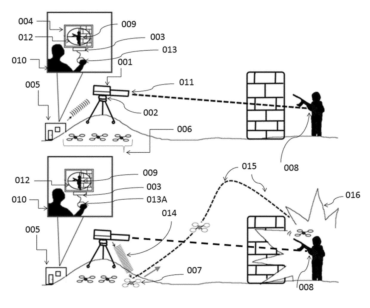
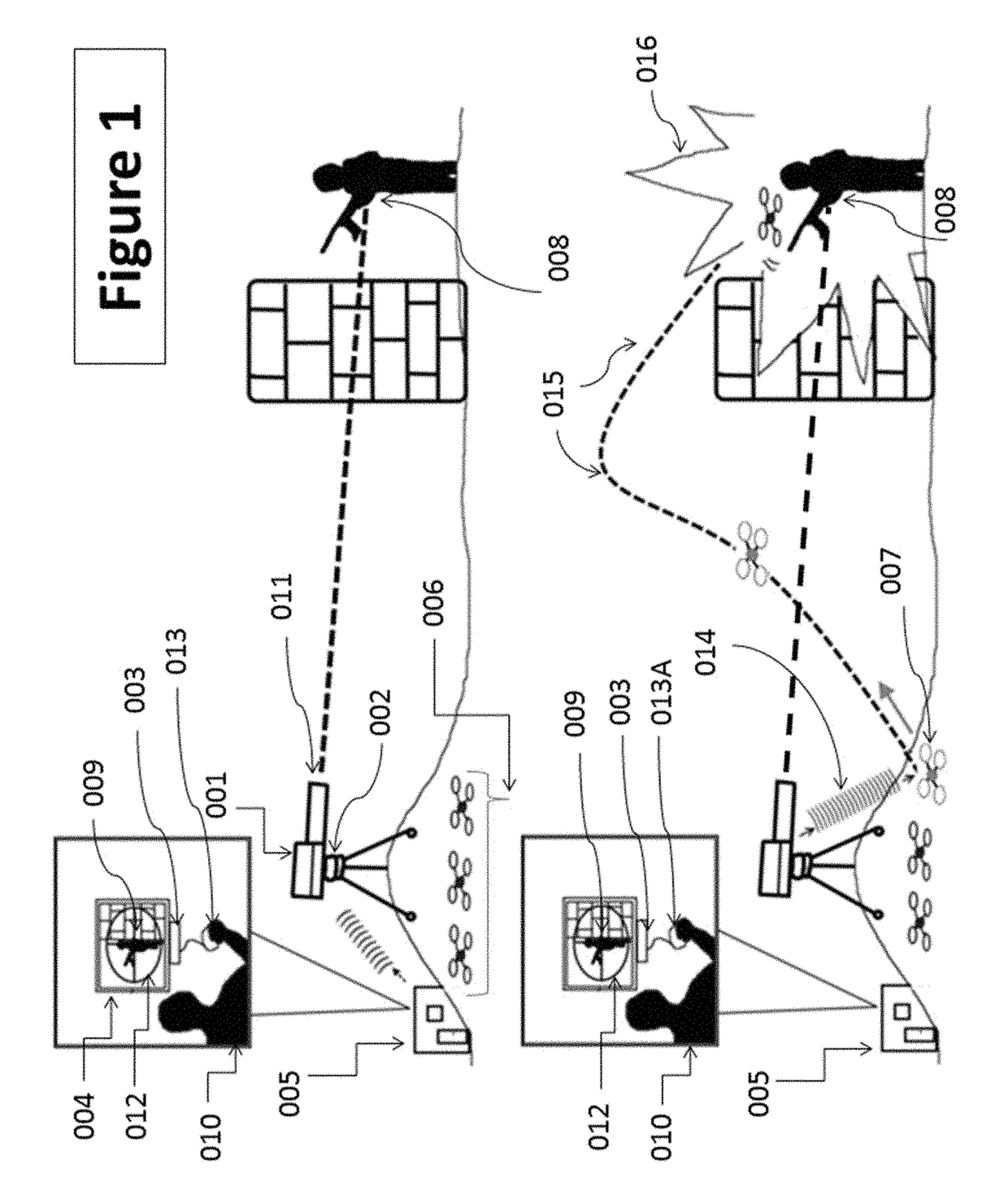
[0031]FIG. 1 illustrates an unmanned sighting and launching system consisting of a portable sighting device (001) coupled to a gimbaled robotic platform (002), a user-controlled device such as a personal computer (003) that displays and controls the field of view (004) of the portable sighting device from a remote location (005); and a plurality of aerial smart drones (006) each of which act as a precision-guided munition (PGM) that can be launched from a point of origin (007) to a precise target coordinate (008). In this illustration the drones act as a smart bomb munition, which is configured to immediately explode (016) when arriving within close-proximity to the precise target coordinate (008). The portable sighting device (001) allows the shooter (010) to safely view his targets from a remote location (005). The portable sighting device in this illustration consists of a powerful telescopic optical assembly (011) which allows the shooter to zoom-in on a target while the gimbale...


PUM


Abstract

A sighting and launching weapons system that incorporates the technologies of smart munitions and virtual reality (VR) simulation with precise target engagement capabilities; including targets that would normally be hidden from the shooter's field of view. Non-linear deployment of smart munitions to a precise target coordinate (via closed-loop navigation) allows for minimal collateral damage. Network link allows a plurality of operators to participate in coordinated target engagement in real time from one or more remote locations. The sighting and launching weapons system can be configured for a variety of uses including the deployment of weaponry or aid, and is capable of automatically identifying friendly targets from enemy targets.

Description

RELATED U.S. APPLICATION DATA[0001]This application is a continuation-in-part of U.S. patent application Ser. No. 13 / 925,620, filed on Jun. 24, 2013, now U.S. Pat. No. 9,310,165, entitled “PROJECTILE SIGHTING AND LAUNCHING CONTROL SYSTEM”, which is a continuation-in-part of U.S. patent application Ser. No. 12 / 607,822, filed on Oct. 28, 2009, now U.S. Pat. No. 8,468,930, entitled “SCOPE ADJUSTMENT METHOD AND APPARATUS”, which is a continuation-in-part of U.S. patent application Ser. No. 11 / 120,701, filed on May 3, 2005, now U.S. Pat. No. 7,624,528, entitled “SCOPE ADJUSTMENT METHOD AND APPARATUS”, which is a continuation-in-part of U.S. patent application Ser. No. 10 / 441,422, filed on May 19, 2003, now U.S. Pat. No. 6,886,287, entitled “SCOPE ADJUSTMENT METHOD AND APPARATUS”, which claims priority from U.S. provisional application Ser. No. 60 / 381,922, filed on May 18, 2002, each of which is expressly incorporated by reference herein in its entirety.BACKGROUNDField of the Disclosure[0...

Claims


Application Information

Patent Timeline
IPC IPC(8): F42B15/01G05D1/00F41G9/00B64C39/02
CPCF41G9/002B64C39/024G05D1/0022F42B15/01B64C2201/128B64C2201/121B64C2201/141G05D2201/0209F41G3/02F41G7/303F41G7/308B64U2101/15B64U2101/60B64U2201/10
Inventor BELL, JOHN CURTISBELL, CURTIS KINGBELL, DAVID ROGERS
Owner BELL JOHN CURTIS
Why Eureka
Try Eureka