System and method of deploying an elongate unit in a body cavity

a technology of elongation unit and body cavity, which is applied in the field of surgical methods and devices, can solve the problems of reducing the triangulation of the port, affecting the accuracy of the manipulator, so as to facilitate the accurate and rapid engagement of the manipulator's distal end

Inactive Publication Date: 2018-08-21
TELEFLEX LIFE SCI LTD
View PDF300 Cites 1 Cited by
  • Summary
  • Abstract
  • Description
  • Claims
  • Application Information

AI Technical Summary

Benefits of technology

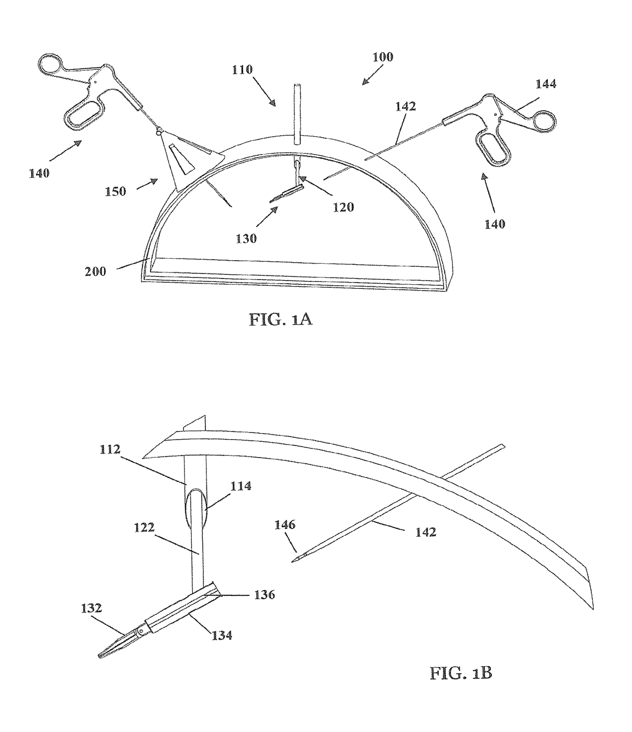
[0016]In a broad aspect of some embodiments there is provided a laparoscopic system applicable for delivering, guiding and / or coupling an interchangeable laparoscopic end-effector (e.g., surgical tool) to a distal portion of a tool manipulator in a body cavity. Appropriately utilizing the system may constitute a shorter duration, reduced uncertainty and improved safety of procedure preparation and initiation.
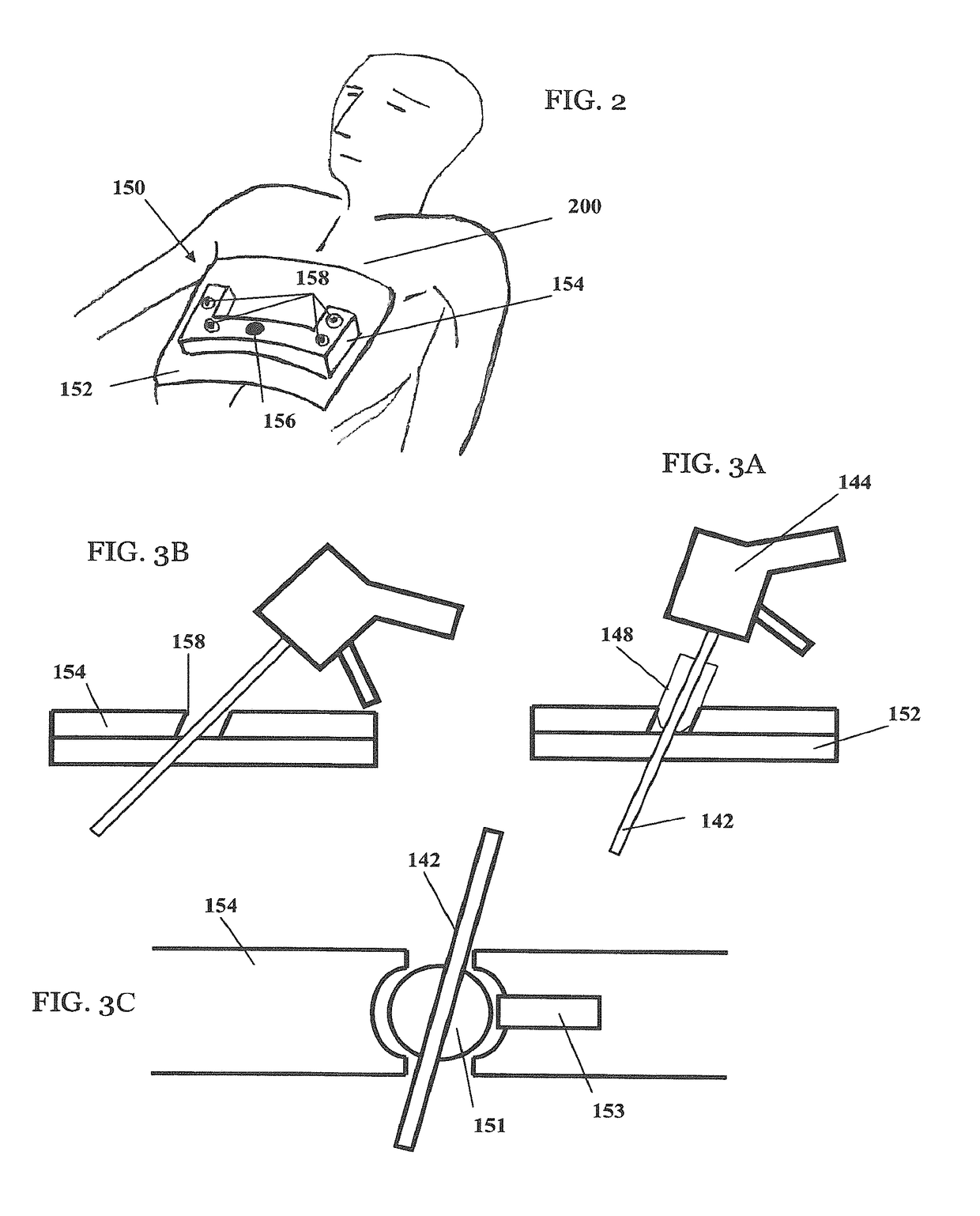
[0020]In some embodiments, the laparoscopic system includes an external guiding template indicating specific insertion ports for trocar and / or manipulators. Optionally, each port is specifically designed to guide a manipulator to a specific orientation within body for a rapid and accurate in-vivo coupling to an interchangeable end-effector. The operator may selectively choose between a fixed manipulator guiding, that is relevant for manipulator introduction into body and engaging with the effector, and a free manipulator movement, relevant for proper surgical intervention. A template frame may be procedure-specific and / or patient-specific (and allow all possible relevant ports) or adjustable according to need. It may be operated manually and / or remotely. Beneath or included in the template frame, there may be an adhesive sealant cloth and / or pad that provides adequate sealing around port / incision to avoid contamination and CO2 leakage.
[0022]In some embodiments, the laparoscopic system includes a surgical tool vectoring mechanism selectively and / or automatically altering introducer distal end when / after the effector is protruding into body through the trocar, in order to facilitate accurate and rapid engagement with manipulator distal end. The vectoring mechanism may allow an accurate, timely direction shift of the surgical tool / effector with respect to tool-holder longitudinal axis. Optionally, the tool is detachable from the introducing tool holder, and is further connectable to a second tool holder (e.g., a manipulator) that is substantially parallel and / or collinear and / or concentric with respect to a receiving portion of the tool / adaptor after the said direction shift. The vectoring mechanism may be passive (e.g., using a spring / nitinol set to shift the tool to a predetermined direction), or active / adjustable (e.g., either mechanically—for example by maneuvering the introducing tool holder along the trocar path, or electronically / robotically—after the tool is completely protruding through the trocar).

Problems solved by technology

Although usually considered superior in several aspects to open surgery, the use of plurality of 5 to 15 mm ports still leads to local pain, scars, and possibly port related complications such as hernia in scars and the need for one or two assistants in addition to the surgeon.
Highly experienced and skilled physicians may still use standard laparoscopic hand instruments, although the use of a single port access decreases its triangulation and complicates maneuverability.
The use of special-purpose articulating instrumentation was introduced to overcome this difficulty, although it is considered very expensive, necessitates special training and still involves complex surgical maneuverability.
The vision is partially obscured by the paralleled inserted instruments; there is minimal triangulation and limited maneuverability of the surgical instruments.
The small instruments have very slender tips which make dissection and tissue maneuvration very difficult.
Furthermore the instrument tips may have a greater tendency to break and their removal may be cumbersome and difficult.
However, patient safety of the aforementioned prior art devices, systems and methods may be improved as navigation precision is not optimal as organs may unintentionally be injured.

Method used


Image

  • System and method of deploying an elongate unit in a body cavity
  • System and method of deploying an elongate unit in a body cavity
  • System and method of deploying an elongate unit in a body cavity

Examples


Embodiment Construction

[0078]Specific embodiments of the invention now will be described with reference to the accompanying drawings. This invention may, however, be embodied in many different forms and should not be construed as limited to the embodiments set forth herein; rather, these embodiments are provided so that this disclosure will be thorough and complete, and will fully convey the scope of the invention to those skilled in the art. The terminology used in the detailed description of the embodiments illustrated in the accompanying drawings is not intended to be limiting of the invention. In the drawings, like numbers refer to like elements.

(a) Exemplary Rapid Laparoscopy System

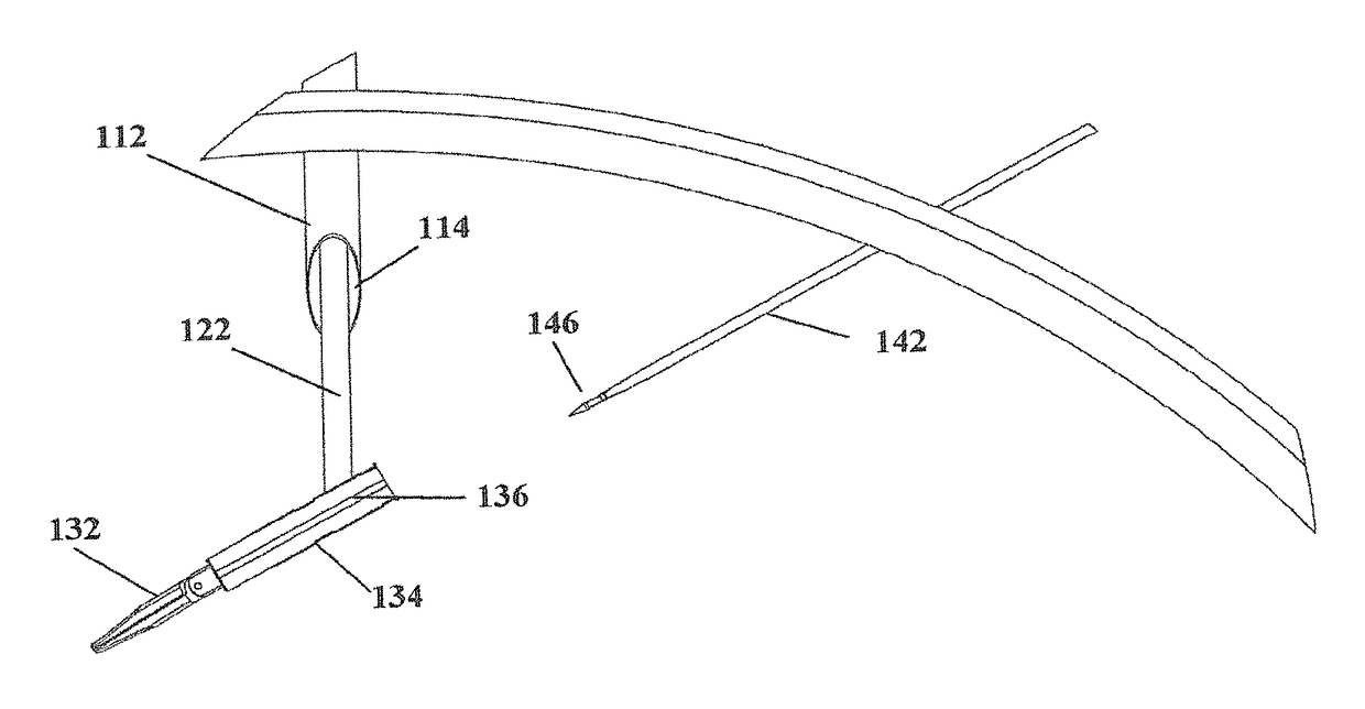
[0079]FIG. 1 illustrate an exemplary rapid laparoscopy system 100 deployed in patient body 200 (shown in a “sliced” proportion for demonstrative purposes), the system includes an introducing sleeve 110 and at least one tool manipulator 140. In some embodiments, sleeve 110 is a trocar having a tubular body 112 and a substan...


PUM


Abstract

A system and method are disclosed for deploying an elongated unit in a body cavity, for introducing an interchangeable tool to a slender shaft having a distal end. The system comprising: an elongated unit comprising a longitudinal axis and a distal portion arranged to protrude through a first port into the body cavity. At least one maneuvering unit connected to the elongated unit for maneuvering the distal portion of the elongated unit in a 3D coordinate system to a determined depth and orientation in the body cavity. The at least one maneuvering unit is arranged to selectively deploy the distal portion of the elongated unit at the determined depth and orientation at a distance with respect to the distal end of the slender shaft and selectively align the longitudinal axis thereof with a longitudinal axis of the slender shaft. The elongated unit and / or the slender shaft is arranged advanceable relative each other, such that once the distal portion of the elongated unit is deployed the distal portion of the elongated unit reaches and / or captures the distal end of the slender shaft.

Description

RELATED APPLICATIONS[0001]This application is a national phase filing under 35 U.S.C. 371 of International Application No. PCT / IB2011 / 050264, filed on Jan. 20, 2011, and claims the benefit of U.S. Provisional Application Ser. No. 61 / 296,485, filed Jan. 20, 2010 and U.S. Provisional Application Ser. No. 61 / 384,288, filed Sep. 19, 2010, the entirety of these applications are hereby incorporated herein by reference for the teachings therein.BACKGROUND OF THE INVENTION[0002]Field of the Invention[0003]The present invention generally relates to surgical methods and devices, and more specifically to laparoscopic and / or any endoscopic related surgical interventions. More particularly, the invention pertains to a system and / or method for deploying an elongated unit in a body cavity.[0004]Description of Prior Art[0005]Laparoscopic or minimally invasive surgery includes the use of several relatively small ports into the abdomen by which different types of instrumentation and accessories are i...

Claims


Application Information

Patent Timeline
Patent Type & Authority Patents(United States)
IPC IPC(8): A61B17/00A61B17/34A61B90/30A61B17/04A61B17/29A61B90/11
CPCA61B17/00234A61B17/3403A61B90/30A61B17/0469A61B2017/2931A61B2017/00283A61B2017/00353A61B2017/00362A61B2017/00473A61B90/11
Inventor FARIN, DANNYBACHAR, YEHUDAWINSHTEIN, RONNYSHOHAT, SHAUL
Owner TELEFLEX LIFE SCI LTD
Why Eureka
Try Eureka