Systems and methods for optical sensor arrangements

a technology of optical sensor and optical arrangement, applied in the field of optical sensor arrangement, can solve the problems of unwarranted increase in electrical design requirements and/or serious affecting monitoring accuracy and power requirements

Active Publication Date: 2018-08-28
BEIJING SHUNYUAN KAIHUA TECH LTD
View PDF17 Cites 0 Cited by
  • Summary
  • Abstract
  • Description
  • Claims
  • Application Information

AI Technical Summary

Benefits of technology

The patent describes a device that uses LEDs and a photodiode for optical measurements. The components can be mounted on printed circuit boards, and the lenses can be positioned at the outside of the device. To prevent direct detection of the LED light by the photodiode, the device has a structure that extends inward from the outside to contact the printed circuit. This structure is further isolated from the photodiode by a layer of opaque tape or sponge-like material. The technical effect of this invention is to provide a reliable and accurate optical measurement system that can be easily installed and configured for various measurement needs.

Problems solved by technology

Otherwise, the photo detector will receive optical energy that is not modulated by heartbeat, which can result in an unwarranted increase in electrical design requirements and / or seriously affect monitoring accuracy and power requirements.

Method used


Image

  • Systems and methods for optical sensor arrangements
  • Systems and methods for optical sensor arrangements
  • Systems and methods for optical sensor arrangements

Examples


Embodiment Construction

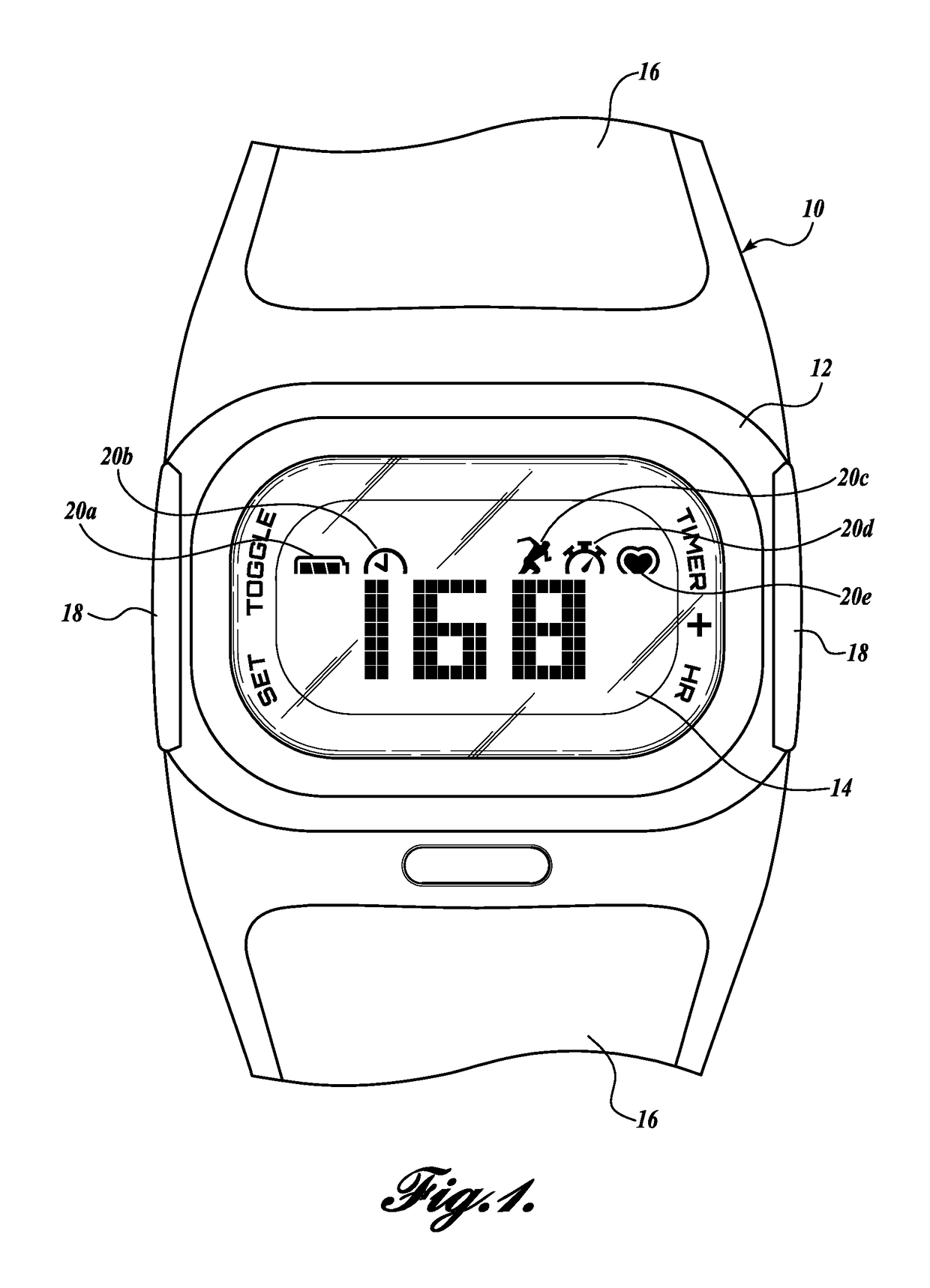
[0021]Shown in FIG. 1 is an apparatus 10 comprising an optical sensor and components for processing and displaying a physiological parameter of a user, as well as other information that may or may not be directly related to the user's activity or environment. In one embodiment, the physiological parameter may be heart rate information. In other embodiments, however, other physiological information may be displayed. As depicted in FIG. 1, apparatus 10 may be a watch, however, apparatus 10 may also be a band, strap, or any other wearable device configured for securing to a user's body or an appendage thereof.

[0022]In one embodiment, apparatus 10 may house a display unit 14 for displaying or otherwise conveying information to the user. In one embodiment, the display unit 14 may comprise a dot matrix liquid crystal display 14. In alternative embodiments, the display unit 14 may comprise some other suitable display or one or more light sources for conveying information. In still further ...


PUM


Abstract

Described herein are systems and methods for mounting optical sensors in a physiological monitoring device worn by a user to sense, measure, communicate, and / or display physiological information. The monitoring devices may be embodied as, for example, a fitness band, a bracelet, a watch, or some other wearable device such as an activity tracker, a health, wellness, or sleep monitor, or an athletic training device. The device may comprise one or more light sources and optical detectors. Optical lenses may be mounted in a face of the device for partially receiving or containing the light sources and optical detectors. The devices and methods described herein may optically isolate the light source(s) from the optical detector(s) to ensure the accurate and reliable detection and measurement of physiological information.

Description

[0001]This non-provisional application claims the benefit of priority to U.S. Provisional Patent Application No. 61 / 976,388, filed Apr. 7, 2014, which is expressly incorporated herein by reference.FIELD OF THE DISCLOSURE[0002]The embodiments relate generally to systems and methods that use non-invasive electro-optical technology for sensing and measuring physiological parameters. More particularly, the embodiments relate to arrangements for the mounting of optical sensors in physiological monitoring devices that are worn by a user.BACKGROUND[0003]Numerous portable devices have been developed in which optical sensors are used to detect, measure, and display various physiological parameter information of a user. For example, some devices detect and measure the variation in blood flow through arteries or blood volume in subcutaneous tissue. Applications for such optical sensors include the monitoring of heart rate, glucose level, apnea, respiratory stress, and other physiological condi...

Claims


Application Information

Patent Timeline
Patent Type & Authority Patents(United States)
IPC IPC(8): A61B5/024A61B5/00A61B5/026
CPCA61B5/02427A61B5/0261A61B5/681A61B2562/0233A61B2560/0462
Inventor FEI, MING SHUN
Owner BEIJING SHUNYUAN KAIHUA TECH LTD
Why Eureka
Try Eureka