Method and device for manufacturing profiled metal strips

a metal strip and profile technology, applied in the direction of manufacturing tools, metal rolling stands, metal rolling arrangements, etc., can solve the problems of high cost of metal forming techniques and method that has not prevailed in practical applications

Active Publication Date: 2018-08-28
OUTOKUMPU NIROSTA
View PDF17 Cites 0 Cited by
  • Summary
  • Abstract
  • Description
  • Claims
  • Application Information

AI Technical Summary

Problems solved by technology

However, this metal forming technique is associated with high costs.
This method has not prevailed in practical applica

Method used


Image

  • Method and device for manufacturing profiled metal strips
  • Method and device for manufacturing profiled metal strips
  • Method and device for manufacturing profiled metal strips

Examples


Embodiment Construction

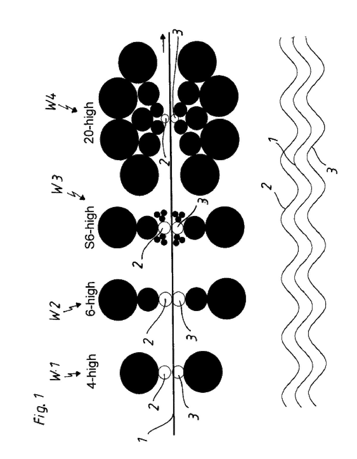
[0052]FIG. 1 shows a schematic diagram of several exemplary rolling stands W1 to W4, by means of which diverse profiles can be produced in a metal strip 1 consisting, for example, of stainless steel. In this context, the topography of the upper working roll 2 and the lower working roll 3 that effectively interact directly with the metal strip 1 is particularly important. The respective rolling stands W1, W2, W3, W4 are illustrated in the form of a side view. The metal strip 1 is guided through the respective rolling stands W1 to W4 in the direction of the arrow.

[0053]The lower portion of FIG. 1 shows the topographies of the upper working roll 2, the lower working roll 3 and the metal strip 1 passing between these working rolls, wherein the topographies are illustrated in the form of a longitudinal view in this case. In this example, the metal strip 1 should be provided with a wave structure.

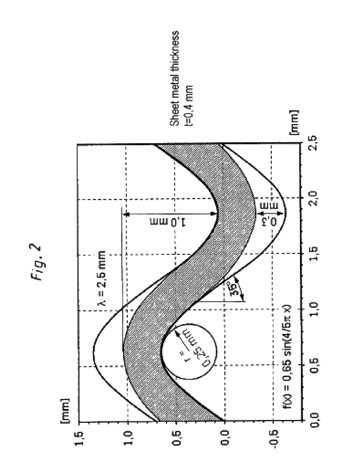
[0054]FIG. 2 shows a chart of the deformation criteria of a metal strip in order to produce a...


PUM

PropertyMeasurementUnit
Lengthaaaaaaaaaa
Lengthaaaaaaaaaa
Fractionaaaaaaaaaa

Abstract

The invention relates to a method for manufacturing profiled metal strips (1, 1′), in which a metal strip (1, 1′) with predefinable material thickness consisting, in particular, of stainless steel is wound up on a coil (4) and guided through a rolling stand (W1-W4) containing several rolls (2, 3, 2′, 3′), wherein at least the rolls (2, 3) that effectively interact with the metal strip (1, 1′) are provided with a predefinable topography (8, 9), by means of which profiles with profile depths >250 μm can be produced on both sides of the metal strip (1, 1′) depending on the geometry of the topography (8, 9) of the rolls (2, 3), and wherein the metal strip (1, 1′) is subsequent to its profiling wound up on a coil (5) and, if so required, subjected to a thermal post-treatment.

Description

CROSS-REFERENCE TO RELATED APPLICATION[0001]This is a national stage application filed under 35 U.S.C. 371 based on international Application No. PCT / EP2013 / 077359 filed Dec. 19, 2013 and claims priority under 35 U.S.C. 119 of German Utility Patent Application No. 10 2012 024 808.3 filed Dec. 19, 2012.STATE REGARDING FEDERALLY SPONSORED RESEARCH OR DEVELOPMENT[0002]Not Applicable.THE NAMES OF THE PARTIES TO A JOINT RESEARCH AGREEMENT[0003]Not Applicable.INCORPORATION-BY-REFERENCE OF MATERAL SUBMITTED ON A COMPACT DISC OR AS A TEXT FILE VIA THE OFFICE ELECTRONIC FILING SYSTEM (EFS-WEB)[0004]Not Applicable.STATEMENT REGARDING PRIOR DISCLOSURES BY THE INVENTOR OR A JOINT INVENTOR[0005]Not Applicable.BACKGROUND OF THE INVENTION[0006]Not Applicable.[0007]The invention pertains to a method for manufacturing profiled metal strips.[0008]It is generally known to produce profiles in metal bodies by means of metal forming operations. However, this metal forming technique is associated with hig...

Claims


Application Information

Patent Timeline
IPC IPC(8): B21B27/00B21B1/22B21B13/04B21B39/02B21D13/10B21D13/04
CPCB21B27/005B21B1/227B21D13/10B21D13/04B21B39/02
Inventor KRAUTSCHICK, JOCHENTEIPEL, JORNWIEMER, DIRK
Owner OUTOKUMPU NIROSTA
Why Eureka
Try Eureka