Artificial knee joint

a knee joint and artificial technology, applied in the field of artificial joints, can solve the problems of short service life, plastic components near the hinge are still often easily broken, and need replacemen

Active Publication Date: 2018-09-04
UNITED ORTHOPEDIC CORP
View PDF3 Cites 1 Cited by
  • Summary
  • Abstract
  • Description
  • Claims
  • Application Information

AI Technical Summary

Benefits of technology

[0005]Accordingly, an object of the present invention is to provide an endurable and reliable artificial joint to solve the problem in which the screw thread comes loose, causing the artificial joint to become ineffective.
[0013]In one embodiment of the present invention, the artificial joint further comprises a reverse motion preventer provided at a back position behind the fixing part in the fixing direction in a manner that the reverse motion preventer prevents the fixing part from reversing along the fixing direction.
[0016]Via the technical means of the present invention, the artificial joint of the present invention adopts newly developed hinge device which is applied to connect the upper surface and the bottom surface of the cushion member, and the joint-twisting axis is unparallel to the fixing direction, which solves the problem of the fixation being loose after long-term use, leading to the ineffectiveness of the artificial joint. Moreover, the pivot portion of the artificial joint of the present invention bears no burden from human body; instead, loadings caused by exertion or loadings borne by human body are transferred to the receiving device, thereby preventing early damage of the pivot portion due to stress concentration. Furthermore, the receiving device of the present invention is designed in a way that it receives the femur connecting device and the tibia connecting device via large contact area with good wear-resistance, thereby achieving a more stable structure and reducing the damage rate. Besides, the artificial joint of the present invention is easy to be assembled, and can thus lower both the time and difficulty of the implant surgery.

Problems solved by technology

A prior artificial hinge joint in the early years simply comprises a hinge component and a fixed bone shank, and has short service life.
However, since the third generation of artificial hinge joint still utilized hinge for transferring force in a way similar to the two previous generations, fracture problem still exists, in which plastic components near the hinge is still often easily broken and thus needs replacement.
However, in the above-mentioned model, the hinge post includes a screw thread parallel to the rotational direction of the artificial joint, causing the potential risk of the hinge post coining loose and falling off from the joint, which further causes the artificial joint to become ineffective.

Method used


Image

  • Artificial knee joint
  • Artificial knee joint
  • Artificial knee joint

Examples


Embodiment Construction

[0024]The preferred embodiments of the present invention are described below with reference to FIG. 1 to FIG. 6. The description is only for explaining the preferred embodiments of the present invention, but not for limiting the implementation of the present invention.

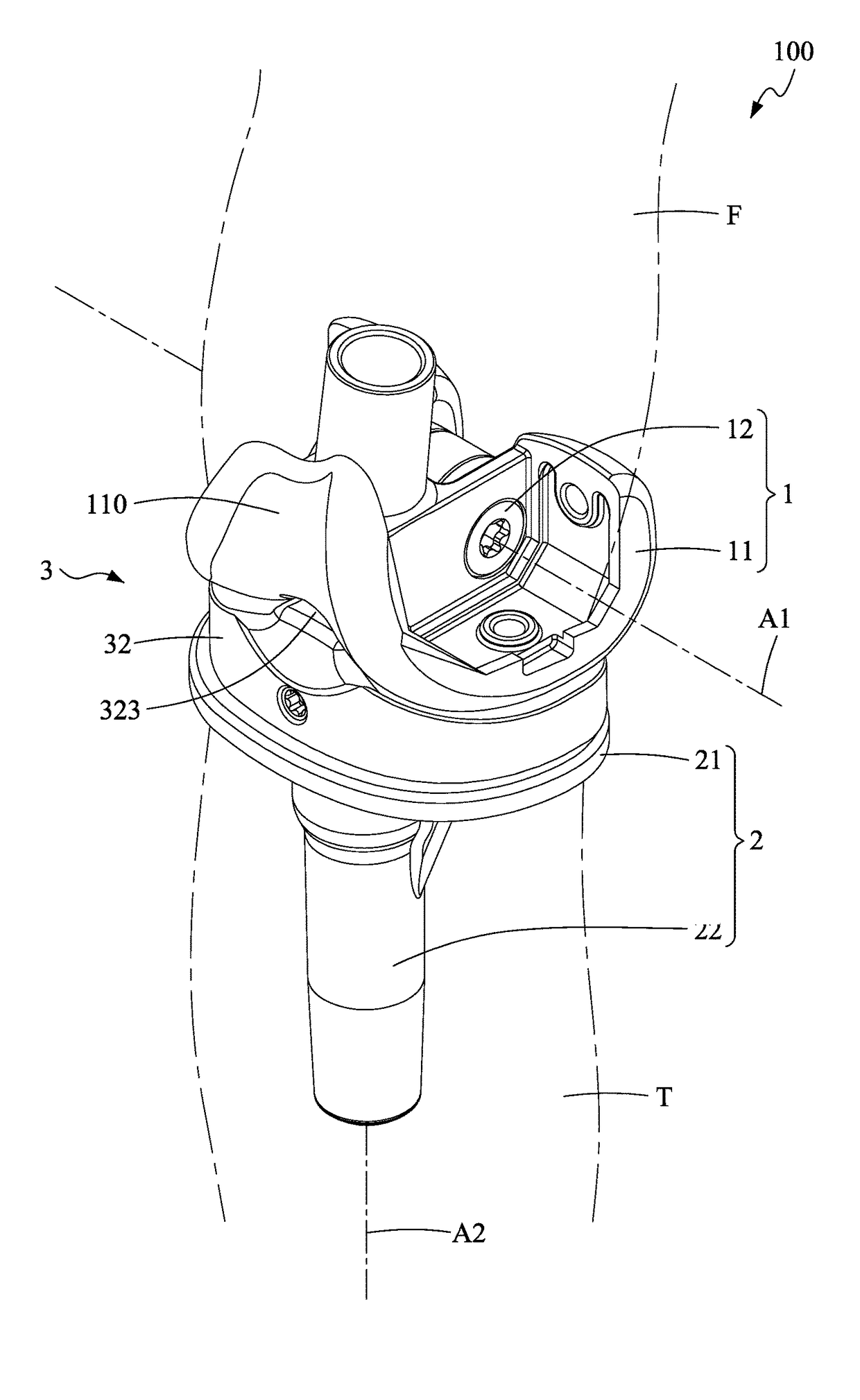
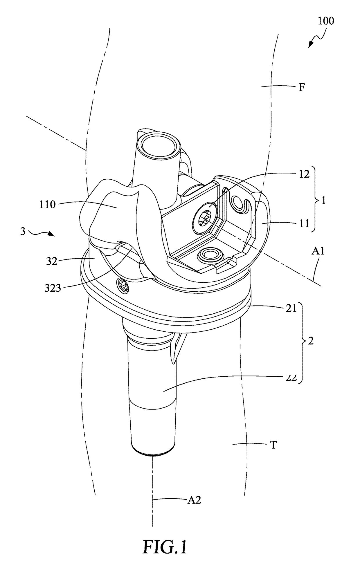
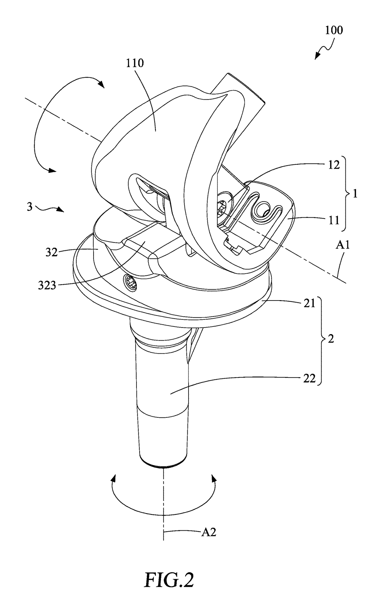
[0025]As shown in FIG. 1, an artificial joint according to one embodiment of the present invention includes a femur connecting device 1, a tibia connecting device 2, and a receiving device 3.

[0026]As shown in FIG. 1 to FIG. 3, the femur connecting device 1 an upper part of the artificial joint 100 and comprises a femur implanting member 11 and an assembly member 12. The femur implanting member 11 is used to connect the artificial joint to a femur F, and is made to simulate the geometric structure of the femur. The femur implanting member 11 includes a smooth condyloid surface 110. The assembly member 12 includes a pivot portion 121 and an assembly portion 122 protruding downward from the pivot portion 121. The pivot po...


PUM


Abstract

The present invention provides an artificial joint, including a femur connecting device, a tibia connecting device, and a receiving device, wherein the femur connecting device is connected and fixed with the receiving device and the tibia connecting device via a fixing member unparallel to a joint-twisting axis, and wherein cushion member receives the femur connecting device via a pivot-receiving surface and receives the tibia connecting device via a twist-receiving surface, thereby providing an durable and reliable artificial joint.

Description

FIELD OF THE INVENTION[0001]The present invention relates to an artificial joint, and more particularly to an endurable and reliable artificial joint.BACKGROUND OF THE INVENTION[0002]Artificial joint is a kind of artifacts implanted into human body to replace natural human knee joint that becomes dysfunctional due to accidental injury, impairment or degeneration on account of fatigue, skeletal variations. There are various types of artificial joints, one of which is artificial hinge joint. Artificial hinge joint has been utilized since 1940s as an implant being implanted into human body to heal diseases such as bone defect or soft tissue dysfunctional.[0003]A prior artificial hinge joint in the early years simply comprises a hinge component and a fixed bone shank, and has short service life. Since 1970s, the second generation of artificial hinge joint is made axially rotatable and used metal or polyethylene as bearing interface, which helps lengthen the service life of artificial jo...

Claims


Application Information

Patent Timeline
Patent Type & Authority Patents(United States)
IPC IPC(8): A61F2/38
CPCA61F2/384A61F2/3886A61F2/3868A61F2/389A61F2/385A61F2/30744A61F2002/30331A61F2002/30364A61F2002/30507
Inventor LU, CHENG-KUANG
Owner UNITED ORTHOPEDIC CORP
Why Eureka
Try Eureka