
HVAC apparatus, method, and system

a technology of hvac equipment and equipment, applied in the field of hvac equipment, can solve the problems of limited installation locations and spaces, many factors that need to be considered, and achieve the effect of improving the state of the ar

Active Publication Date: 2018-09-11
AUBURN UNIV
View PDF21 Cites 17 Cited by
  • Summary
  • Abstract
  • Description
  • Claims
  • Application Information

AI Technical Summary

Benefits of technology

The technical effect of this patent is to improve the state of the art in the field of HVAC systems by solving problems and deficiencies that exist in the current technology.

Problems solved by technology

One difficulty with such systems is the many factors that need to be considered when designing, installing, and operating such systems.
However, this is antagonistic to limited space availability in certain circumstances (for example high density apartment complexes).
There simply may be limited installation locations and spaces.
There may be building or other codes and regulations that limit options.
Additionally, economic pressures are always in play.
Less efficient systems are antagonistic to energy costs.
Cost of parts, installation, maintenance, and operation may collide with the best heating and cooling delivery.
Still further, options, regulations, needs and desires for HVAC tend to constantly change.
However, in light of the substantial lifetime of many HVAC components, it is expensive to change systems that have not exhausted their useful life.
Furthermore, new standards may not match up with available space, efficiency, or heating and cooling in certain applications.
Therefore, although many basic HVAC components can be purchased commercially, because of the variety of factors that must be considered, substantial amount of customization is required most times. The installer may end up having to select different components for each application if there are multiple installations or configurations in the same building or facility.
Customization can require additional labor and materials cost.
Although HVAC technology is a relatively mature industry, again, there are a number of competing factors which leave room for improvement or innovation.
One issue with these conventional HVAC systems is efficiency.
Additionally, the more work required of the system, the more energy is consumed.
Some of these costs can fluctuate over time.
They can impose substantial financial burden.
Government policy, consumer demand, or other influences can complicate this issue.
Compliance may be difficult with conventional systems.
Another issue can be space and location requirements for HVAC equipment that meet new efficiency requirements.
But it may be difficult to do with conventional systems.
For example, if government regulations demand a certain performance level for an HVAC system for a multi-unit apartment building, present conventional components may not fit within present mounting locations.
To make them fit, substantial and costly major remodeling of the building might be required.
And this issue may exist not only for installation of an HVAC system, but also hinder operation, maintenance, or repair.
For example, just because a system might technically fit in a location, it may be impractical or impossible to adequately service or repair the system.
Access to critical internal components might be blocked.
This requires vendors and manufacturers to have a wide variety of inventory for different HVAC needs, or may require substantial resources (cost, time, labor, etc.) to either customize the HVAC equipment or renovate the installation space.
Still further, HVAC systems and components have a substantial rated lifespan.
Over that time period, replacement parts may no longer be available.
Other factors may result in the inability or impracticality of repairing or replacing the same or similar equipment into the same space and orientation.
Stated differently, it many times is not possible to do an HVAC installation today that could have been done ten or even five years ago.
Yet with changing regulations and consumer demand, perhaps millions of such systems will have to be replaced in the near future.
There is a serious issue whether this will be economically possible using conventional HVAC technology.
Solutions can be difficult because of the sometimes competing factors that must be taken into consideration, including not only efficiency of operation but cost of materials, assembly, maintenance, and repair over the relatively long life of such systems.

Method used


Image

  • HVAC apparatus, method, and system
  • HVAC apparatus, method, and system
  • HVAC apparatus, method, and system

Examples


Embodiment Construction

[0072]A. Overview

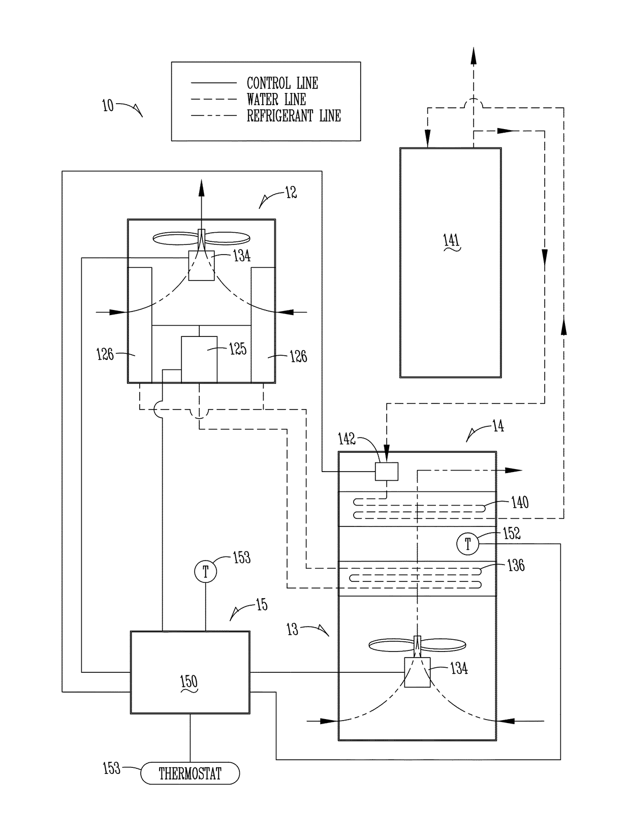
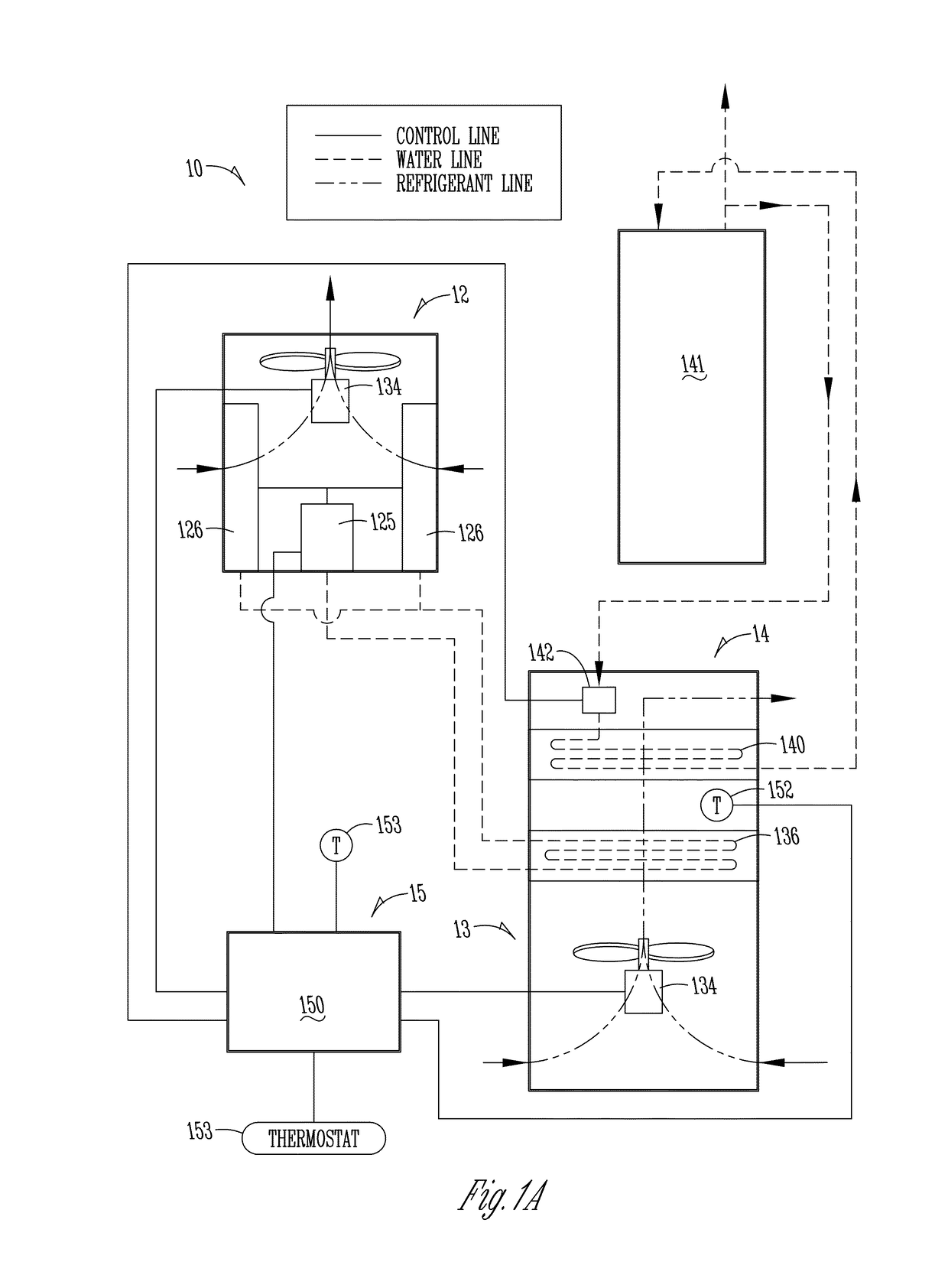
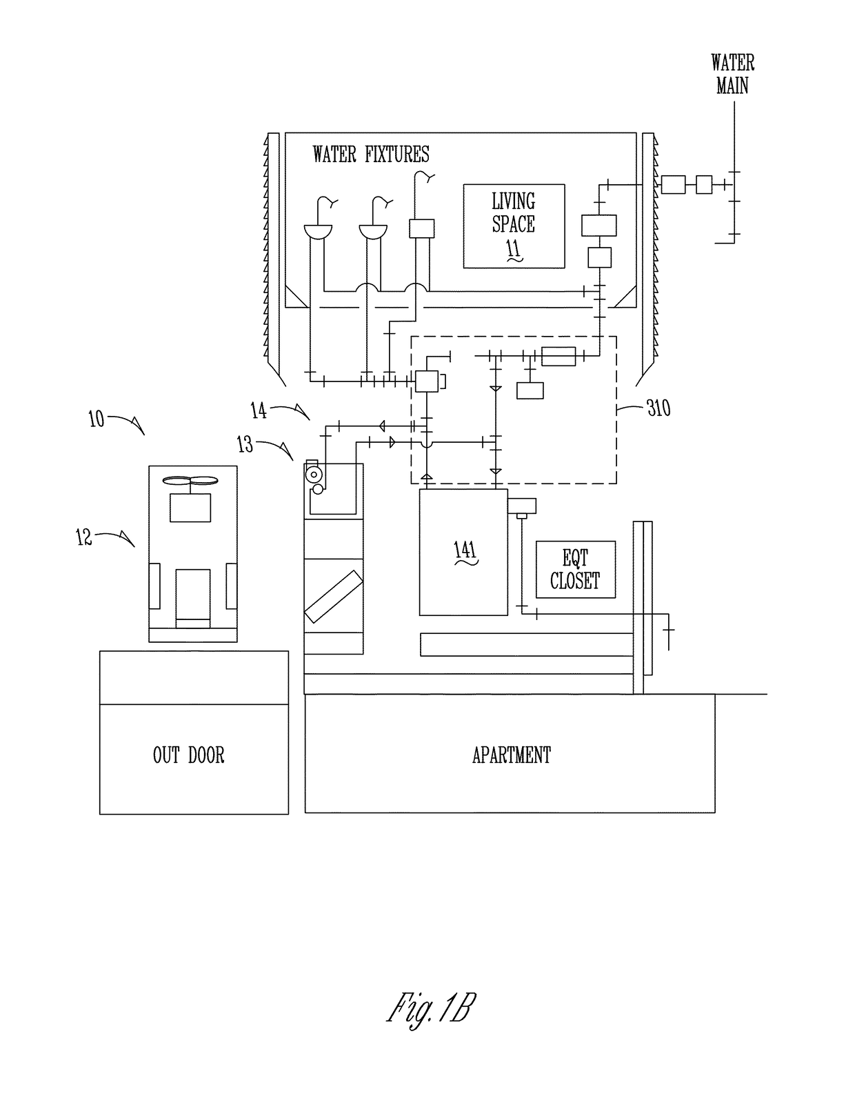
[0073]For a better understanding of the invention, examples of specific forms the invention and its aspects can take will now be described in detail. These examples are neither inclusive nor exclusive of all forms the invention and its aspects can take. Variations obvious to those skilled in the art will be included within the invention which is solely described by the appended claims. These exemplary embodiments will be described in the context of an HVAC system including a commercially available outdoor refrigeration-based heat pump, an indoor air handler component that supplies or is connected to duct work to supply conditioned air to an indoor space, a supplemental or booster heat supply, in this example, a hydronic subsystem, and a control subsystem to operate the components. These examples will primarily be in the context of the indoor air handler subsystem principally housed in a highly configurable but highly efficient assembly which can receive conventional...


PUM


Abstract

The invention relates to an HVAC apparatus, method, and system. Aspects of the invention include a supplemental heat source with an air handler unit for a conventional forced air heating and cooling system. The supplemental heat source in one example is a hydronic subsystem. It can be used alone or to supplement the forced air subsystem. Another aspect of the invention includes an air handling subsystem that has a housing that can be highly flexible in configuration and installation. The housing can support internal components, including a hydronic or other supplemental heat source with the forced air components. At least two sides of the housing can be configured for access for maintenance and repair. A control system can be designed to eliminate need for defrost cycle for forced air refrigeration-type subsystem and / or for better maintenance for comfort in the air conditioned space.

Description

CROSS-REFERENCE TO RELATED APPLICATIONS[0001]This application claims priority under 35 U.S.C. § 119 to provisional application Ser. No. 61 / 773,446 filed Mar. 6, 2013, herein incorporated by reference in its entirety.I. BACKGROUND OF THE INVENTIONA. Field of the Invention[0002]The present invention relates to heating, ventilation, and cooling (HVAC) systems, apparatus, and methodologies, and in particular to utilization of a heat pump outside the conditioned air space in combination with a highly configurable air handler subsystem to supply conditioned air effectively, efficiently, and economically to the space.[0003]One primary application of the present invention is to residential spaces such as apartments (including high density configurations), homes, and the like, as well as to analogous spaces.B. Related Art[0004]A wide variety HVAC approaches exist in the marketplace. A wide variety of manufacturers and vendors of HVAC equipment also exist. Many fall along the line of a separa...

Claims


Application Information

Patent Timeline
Patent Type & Authority Patents(United States)
IPC IPC(8): F24F5/00F24D12/02F24D19/10
CPCF24F5/0046F24D12/02F24D19/1087Y02B30/00
Inventor AKIN, JOE A.DYER, DAVID F.
Owner AUBURN UNIV
Learn More