Abnormality diagnosis method and device therefor

a technology of abnormality and diagnosis method, applied in the direction of program control, instruments, testing/monitoring control systems, etc., can solve the problems of running out of available capacity and the decrease in the amount of data that can be sent to the data center

Active Publication Date: 2018-09-11
HITACHI LTD
View PDF13 Cites 72 Cited by
  • Summary
  • Abstract
  • Description
  • Claims
  • Application Information

AI Technical Summary

Benefits of technology

[0015]With the abnormality diagnosis method and device therefor according to the invention, whether or not an amount of sensor data required for causal analysis can be retrieved before the remaining capacity of the storage device storing the sensor data of the machine is predicted, and if the sensor data cannot be retrieved, an instruction to replace the storage device is sent outside. Thus, an abnormality of the machine can be detected and causal analysis thereof can be securely executed.

Problems solved by technology

However, if the drop in the communication speed continues for a long time, the amount of data that can be sent to the data center decreases.
Therefore, the sensor data cannot erased from the storage device installed in the machine, posing the problem of running out of the available capacity.

Method used


Image

  • Abnormality diagnosis method and device therefor
  • Abnormality diagnosis method and device therefor
  • Abnormality diagnosis method and device therefor

Examples


example

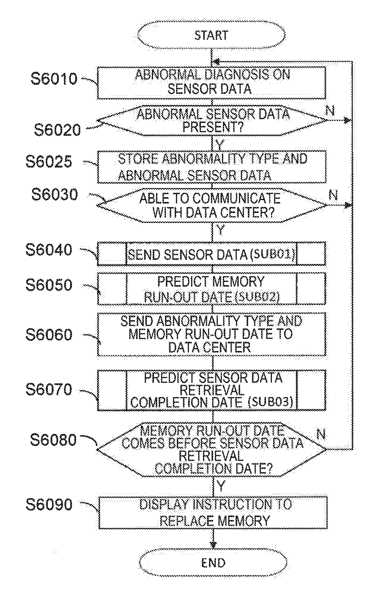
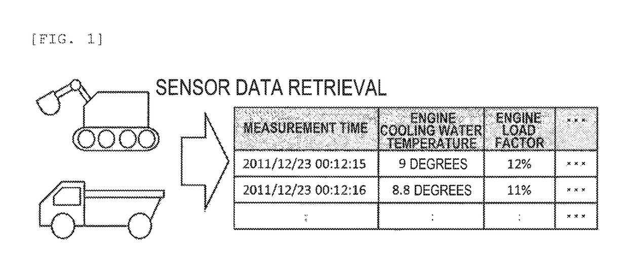
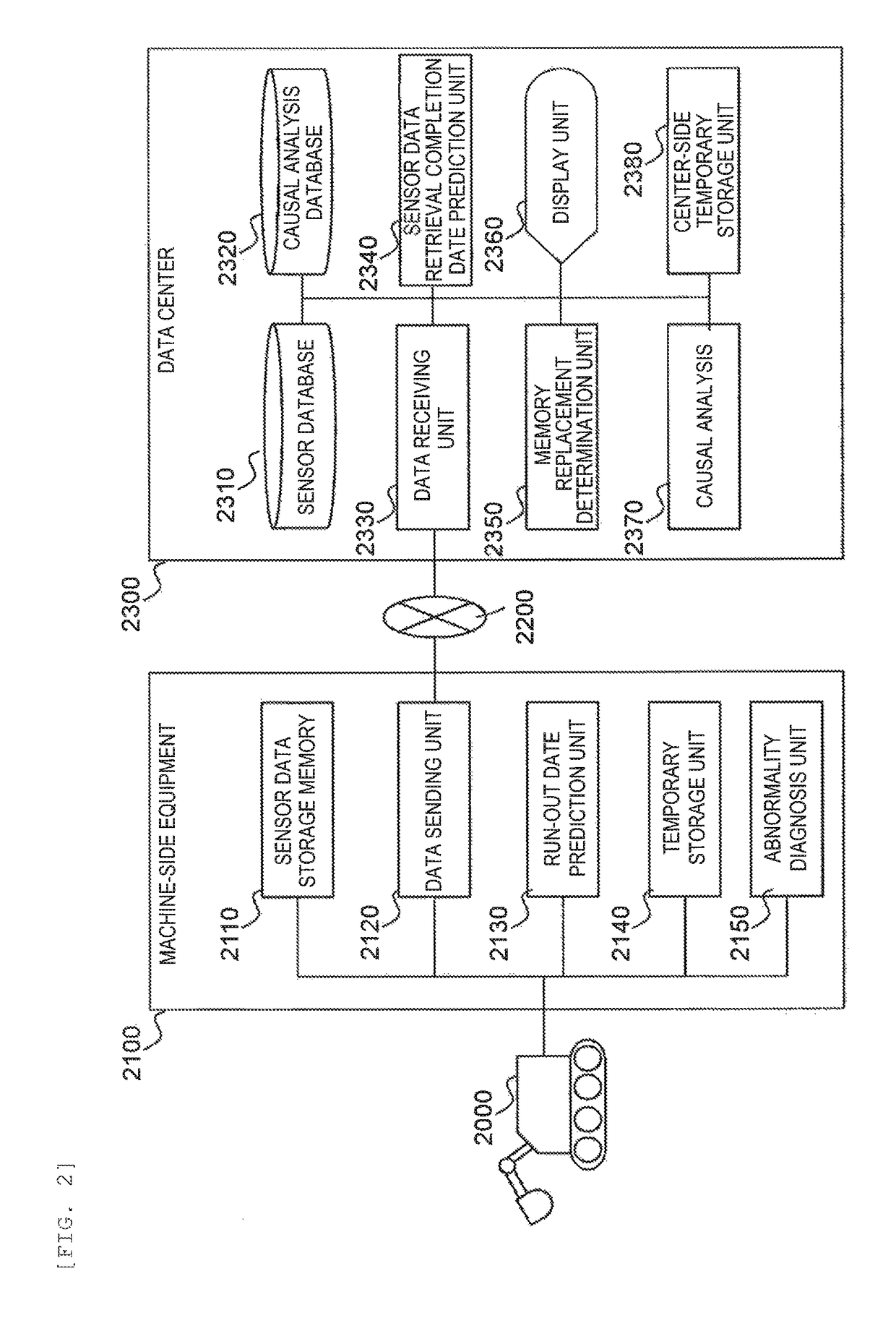
[0033]FIG. 2 shows the overall configuration using a computer system according to the invention. FIG. 3 and FIG. 4 are views explaining the table structures in a database and on a temporary storage unit. FIG. 5 is a view explaining a method for predicting the day on which a storage memory for sensor data runs out of available capacity. FIG. 6, FIG. 7, FIG. 8 and FIG. 9 show processing flows. FIG. 10 shows a screen which instructs the user of a data center to replace the sensor data storage memory of the machine. FIG. 11 shows the table structure of sensor data stored in the sensor data storage memory.

[0034]In the overall configuration of FIG. 2 showing an example of the invention, a machine 2000 is a machine to be a maintenance target. For example, in the case of a construction machine, a truck or loader, or in the case of an industrial machine, an elevator or the like is equivalent to this.

[0035]Machine-side equipment 2100 is equipment installed on the machine or installed near the...


PUM


Abstract

In industrial machine abnormality diagnosis, if the machine is diagnosed to have abnormality, then sensor data from the machine needs to be sent to a management center for causal analysis. However, since machines operated at a remote site cannot always communicate with a management center, it has been found that, in some cases, sensor data that has failed to be sent from a machine remains in the memory of the machine, resulting in lack of available memory capacity. In view of this, the present invention determines beforehand whether the diagnosed machine will run out of available memory capacity before the completion of sending the amount of sensor data required for causal analysis for the machine, and instructs a maintenance person to recover memory. This determination as to whether the machine will run out of available memory capacity before the completion of sending the amount of sensor data required for the causal analysis for the machine, is made as follows: (1) first, the machine predicts the run-out date on which the machine will run out of memory capacity for storing sensor data generated in the machine, and sends a notification of the predicted run-out date to the management center for the machine; and (2) next, from the amount of sensor data required for the causal analysis and the reception rate of sensor data, the management center calculates the number of days required to retrieve the necessary data for the causal analysis and determines whether the management center can retrieve the data by the predicted run-out date.

Description

TECHNICAL FIELD[0001]The present invention relates to an abnormality diagnosis method in which information about a machine is gathered from sensors attached to each part of the machine and then abnormality diagnosis is carried out, in order to detect an abnormality in the machine and carry out causal analysis thereof, and a device therefor.BACKGROUND ART[0002]In order to allow a machine such as a gas engine, elevator, or mining / construction machine to operate constantly, maintenance work on the machine is essential. One of effective techniques for maintenance work is the technique of gathering sensor data from sensors attached to each part of the machine, then carrying out abnormality diagnosis of the machine on the basis of the gathered sensor data, and carrying out causal analysis of an abnormality if it is found.[0003]To carry out this technique, abnormality diagnosis of the sensor data of the machine is carried out, and if an abnormality is found, the sensor data is gathered at ...

Claims


Application Information

Patent Timeline
Patent Type & Authority Patents(United States)
IPC IPC(8): G05B23/02E02F9/26G07C5/08G07C5/00
CPCG05B23/0283E02F9/267G07C5/008G07C5/085G05B23/0297G05B2219/2616G05B23/0264
Inventor UCHIDA, TAKAYUKISUZUKI, HIDEAKIFUJIWARA, JUNSUKEHIRUTA, TOMOAKIUNUMA, MUNETOSHI
Owner HITACHI LTD
Why Eureka
Try Eureka