Battery unit

a battery unit and battery technology, applied in the field of batteries, can solve the problems of complex circuitry of conventional battery units and complex circuitry of 3 batteries, and achieve the effect of simple circuitry

Inactive Publication Date: 2013-06-13
HITACHT MAXELL LTD
View PDF0 Cites 13 Cited by
  • Summary
  • Abstract
  • Description
  • Claims
  • Application Information

AI Technical Summary

Benefits of technology

[0012]An object of the present invention is to provide a battery unit having simple circuitry and capable of detecting an abnormality in a secondary battery cell.
[0015]In a battery unit according to an embodiment of the present invention, a battery subunit may include a battery module having a secondary battery cell and a fuse connected in series, and a voltage monitoring circuit may monitor the voltage across the terminals of the battery subunit. If a current equal to or less than the rated current of a fuse is flowing through the fuse, the voltage drop across the fuse is several mV. Thus, monitoring the voltage across the terminals of a battery subunit will make it possible to determine whether the secondary battery cell itself is abnormal. Further, the battery unit according to an embodiment of the present invention is capable of detecting an abnormality in a secondary battery cell as correctly as arrangements that monitor the voltage across the terminals of a secondary battery cell.
[0017]Furthermore, in a battery unit according to an embodiment of the present invention, a voltage monitoring circuit may monitor the voltage across the terminals of a battery subunit having a secondary battery cell and a fuse connected in series. Thus, a battery unit according to an embodiment of the present invention has a smaller number of voltage detectors than arrangements that monitor the terminals of each secondary battery cell, resulting in simpler circuitry.

Problems solved by technology

As such, the battery units described in Patent Documents 1 to 3 have complicated circuitry.
Thus, conventional battery units have complicated circuitry.

Method used


Image

  • Battery unit
  • Battery unit
  • Battery unit

Examples


first embodiment

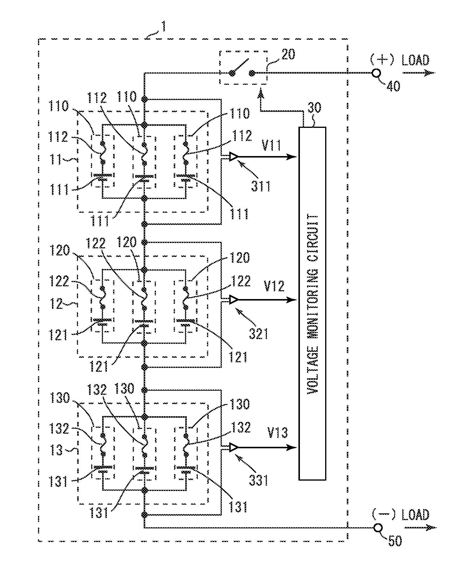
[0029]Referring to FIGS. 1 to 5, a battery unit 1 according to a first embodiment will be described. FIG. 1 is a circuit diagram showing the circuit structure of the battery unit 1 of the first embodiment.

[0030]The battery unit 1 includes battery subunits 11, 12 and 13, a switch 20, voltage detectors 311, 321 and 331, and a voltage monitoring circuit 30. Identification information ID11, ID12 and ID13 are associated with the battery subunits 11, 12 and 13, respectively. The identification information ID11, ID12 and ID13 are information used to identify the battery subunits 11, 12 and 13, respectively.

[0031]The battery subunits 11, 12 and 13 are connected in series between a plus terminal 40 and a minus terminal 50. The battery subunit 11 includes three battery modules 110. The three battery modules 110 are connected in parallel between the switch 20 and the battery subunit 12. Each battery module 110 includes a secondary battery cell 111 and a fuse 112. The secondary battery cell 111...

second embodiment

Variations of Second Embodiment

[0112]In the second embodiment, the battery module 110 includes one secondary battery cell 111, however, the embodiment is not limited to such a configuration. For example, the battery module 110 may include a plurality of secondary battery cells 111 connected in series.

[0113]In the above description, the switch 20 is connected between the positive electrode terminal of the battery subunit 11 and the load, however, the embodiment is not limited to such a configuration. The switch 20 may be connected between the negative electrode terminal of the battery subunit 11 and the load.

Third Embodiment

[0114]Next, referring to FIGS. 9 and 10, a battery unit 1Y of a third embodiment will be described. FIG. 9 is a circuit diagram showing the circuit structure of the battery unit 1Y of the third embodiment.

[0115]The battery unit 1Y of the third embodiment is similar to the battery unit 1 except for replacing the battery subunit 11 of the battery unit 1 shown in FIG...

third embodiment

Variations of Third Embodiment

[0127]In the third embodiment, the battery module 110 includes one secondary battery cell 111, however, the embodiment is not limited to such a configuration. For example, the battery module 110 may include a plurality of secondary battery cells 111 connected in series.

[0128]In the above description, the switch 20 is connected between the positive electrode terminal of the battery subunit 11Y and the load, however, the embodiment is not limited to such a configuration. The switch 20 may be connected between the negative electrode terminal of the battery subunit 11Y and the load.

[0129]In the above description, if the voltage V11Y received from the voltage detector 311Y is zero, the voltage monitoring circuit 30Y turns the switch 20 off (step S53), however, the embodiment is not limited to such a configuration. Step S53 of the third switch control process (FIG. 10) may be eliminated. This is because the battery unit 1Y is not able to supply power to the l...


PUM

PropertyMeasurementUnit
rated currentaaaaaaaaaa
voltageaaaaaaaaaa

Abstract

A battery unit (1) includes battery subunits (11, 12, 13) and a voltage monitoring circuit (30). The battery subunits (11, 12, 13) includes battery modules (110, 120, 130), each having a secondary battery cell (111, 121, 131) and a fuse (112, 122, 132) connected in series. The voltage monitoring circuit (30) monitors the voltage across the terminals of each of the battery subunits (11, 12, 13). Each of the battery subunits (11, 12, 13) includes one battery module or a plurality of battery modules (110, 120, 130) connected in parallel.

Description

TECHNICAL FIELD[0001]The present invention relates to battery units.BACKGROUND ART[0002]JP 2010-67536 A (Patent Document 1) describes a battery pack including a plurality of battery arms in parallel, each battery arm having one or more battery cells and fuses in series, where the voltage at each of the battery cells included in each of the battery arms is measured and, based on this voltage, it is determined whether a fuse has blown (see [0013] and [0016]).[0003]JP 2010-3619 A (Patent Document 2) describes that a control circuit detects a voltage transmitted from the positive electrode of a battery cell and determines whether the detected voltage is within a predetermined range to determine whether the associated battery subunit is abnormal (see [0047] and [0049]).[0004]JP 2004-103483 A (Patent Document 3) describes a plurality of battery subunits in parallel, each battery subunit having secondary battery cells and fuses in series, where the voltage applied to a fuse of a battery su...

Claims


Application Information

Patent Timeline
Patent Type & Authority Applications(United States)
IPC IPC(8): H01M2/34H01M50/574H01M50/583
CPCH01M2/34H01M2200/103H01M10/482Y02E60/10H01M50/583H01M50/574H02J7/0031H01M50/572H01M10/4207
Inventor MATSUO, YUZONAGAI, RYOKAJIYAMA, KOICHI
Owner HITACHT MAXELL LTD
Why Eureka
Try Eureka