Supercharge Your Innovation With Domain-Expert AI Agents!

Serial data link measurement and simulation system

a simulation system and serial data technology, applied in the field of serial data link system analysis, can solve the problems of serial data link high speed signaling for a number of designs and standards, channel or interconnection, unsatisfactory, etc., and achieve the effect of convenient us

Active Publication Date: 2018-09-11
TEKTRONIX INC
View PDF13 Cites 1 Cited by
  • Summary
  • Abstract
  • Description
  • Claims
  • Application Information

AI Technical Summary

Problems solved by technology

Currently high speed signaling for a number of designs and standards for serial data links has become severely channel, or interconnect, limited.
There are several challenges when measuring or debugging the serial data link when operating on a severely limited channel: the channel and the transmitter interact in a complex way; the eye diagram at the receiver is nearly or completely closed; the receiver doesn't discriminate the digital signal directly but only after equalization; etc. FIG. 1 represents a serial data link having a transmitter at one end with transmitter equalization, a transmitter connector, a cable, a receiver connector and a receiver with receiver equalization.
The equalization attempts to recreate the eye diagram as transmitted from the transmitter, but the result is not ideal.
However, the connection of the test instrument to the transmitter, or to any point within the serial data link, presents its own distortions which need to be accounted for in order to produce reliable, usable measurements.
However, none has represented the system in a way that totally and properly ties together all aspects of the serial data link system.
This system does allow full S-parameter modeling, but it does not tie it all together with the overall serial data link model, making it somewhat complex and difficult for a user.
Detail of the processing flow is still somewhat obscure and confusing.
The associated menu view is not optimal for the user in showing how things are connected and how the signal processing flow is implemented.
However, this model does not correctly represent cross-talk, cross-coupling or full cascading of S-parameters from block to block.
However, the Agilent package combines the de-embed and embed blocks into one block each, which may be correct but is difficult to look at and understand since each block must be defined twice, once for the measurement circuit and once for the simulation circuit.

Method used


Image

  • Serial data link measurement and simulation system
  • Serial data link measurement and simulation system
  • Serial data link measurement and simulation system

Examples


Embodiment Construction

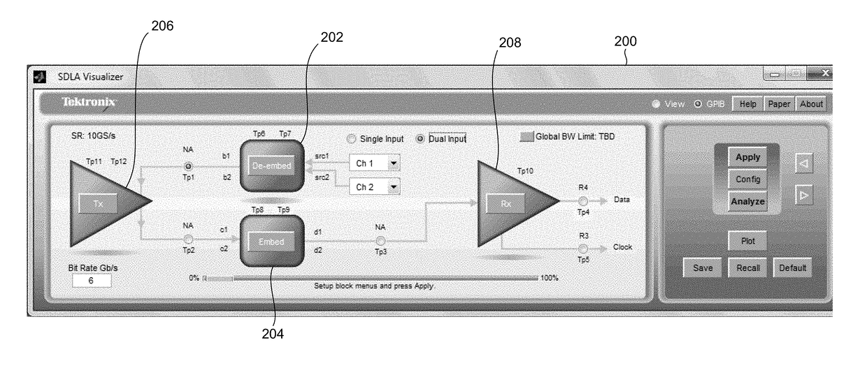
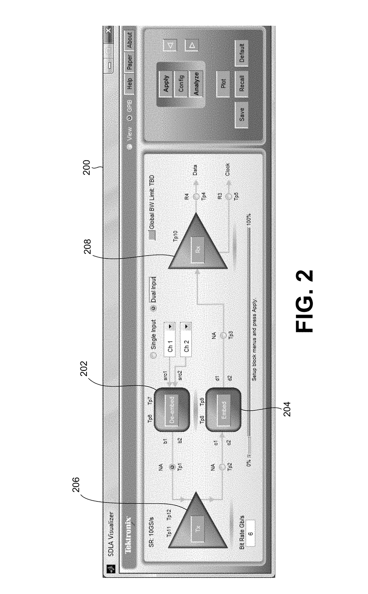
[0025]Referring now to FIG. 2, a main menu according to the present invention is provided on a display 200 of a test and measurement instrument, such as an oscilloscope. The main menu shows two circuit models to be defined by a user, a measurement circuit 202 and a simulation circuit 204, which both connect to a transmitter (Tx) block 206. The Tx block 206 uses a Thevenin equivalent voltage to provide a point where an acquired waveform, as corrected by the measurement circuit 202, is passed into the simulation circuit 204. Thevenin's Theorem states that it is possible to simplify any linear circuit, no matter how complex, to an equivalent circuit with just a single voltage source and impedance.

[0026]The upper part of the main menu of FIG. 2 stemming from the Tx block 206 represents physical components used to obtain the acquired waveform from an input signal, such as probes, test instrument itself, fixtures and the portion of the channel between the Tx block 206 and fixtures. The ma...


PUM


Abstract

A serial data link measurement and simulation system for use on a test and measurement instrument presents on a display device. A main menu having elements representing a measurement circuit, a simulation circuit and a transmitter. The main menu includes processing flow lines pointing from the measurement circuit to the transmitter and from the transmitter to the simulation circuit. The main menu includes a source input to the measurement circuit and one or more test points from which waveforms may be obtained. The simulation circuit includes a receiver. The measurement and simulation circuits are defined by a user, and the transmitter is common to both circuits so all aspects of the serial data link system are tied together.

Description

CROSS-REFERENCE TO RELATED APPLICATIONS[0001]The present application is a non-provisional patent application claiming the benefit of provisional U.S. Patent Application Ser. No. 61 / 658,368, filed Jun. 11, 2012, which provisional U.S. Patent Application is incorporated herein by reference.BACKGROUND OF THE INVENTION[0002]The present invention relates to serial data link system analysis, and more particularly to a serial data link measurement and simulation system analysis interface.[0003]Currently high speed signaling for a number of designs and standards for serial data links has become severely channel, or interconnect, limited. The result is that an eye diagram, which represents a digital signal transmitted over the serial data link, is often closed at the receiver. Equalization methods are used both for the transmitter as well as for the receiver to open the eye diagram and operate the serial data link to assure accurate transfer of digital information from a transmitter to the r...

Claims


Application Information

Patent Timeline
Patent Type & Authority Patents(United States)
IPC IPC(8): G06F17/50G06F11/30H04B3/46H04L25/03
CPCG06F11/30H04B3/46H04L25/03057G06F17/5022G06F30/33
Inventor PICKERD, JOHN J.TAN, KANSEPP, KALEVBOEN, SARAH R.
Owner TEKTRONIX INC
Features
  • R&D
  • Intellectual Property
  • Life Sciences
  • Materials
  • Tech Scout
  • Unparalleled Data Quality
  • Higher Quality Content
  • 60% Fewer Hallucinations
Learn More