Method and apparatus for motor lock or stall detection

a technology of motor lock or stall detection and method, applied in the field of electric motors, can solve the problems of increasing complexity, reducing reliability, and adding cos

Active Publication Date: 2018-09-11
NXP USA INC
View PDF19 Cites 12 Cited by
  • Summary
  • Abstract
  • Description
  • Claims
  • Application Information

AI Technical Summary

Problems solved by technology

However, the absence of mechanical or electrical contact between the stator and rotor of the PMSM or BLDC motors presents challenges with determining the relative positions of the component parts.
One position-indicating arrangement is to use sensors (e.g., incremental encoders) to detect a motor component position status as part of the motor control function, but such sensors add cost and increase complexity (due the additional sensors, wiring, connectors, soldering, etc.), reduce reliability (due in part to the sensor connectors that are prone to contamination from dirt and humidity), and are not suitable for applications (e.g., where the rotor is in closed housing and the number of electrical entries must be kept to a minimum, such as in a compressor, or in applications where the motor is immersed in a liquid such as some pumps).
However, sensorless motor control techniques have a drawback that the rotor mechanical block or stall condition may not be recognized by the sensorless algorithm.
As a result, the existing solutions for detecting locked rotor conditions are extremely difficult at a practical level.

Method used


Image

  • Method and apparatus for motor lock or stall detection
  • Method and apparatus for motor lock or stall detection
  • Method and apparatus for motor lock or stall detection

Examples


Embodiment Construction

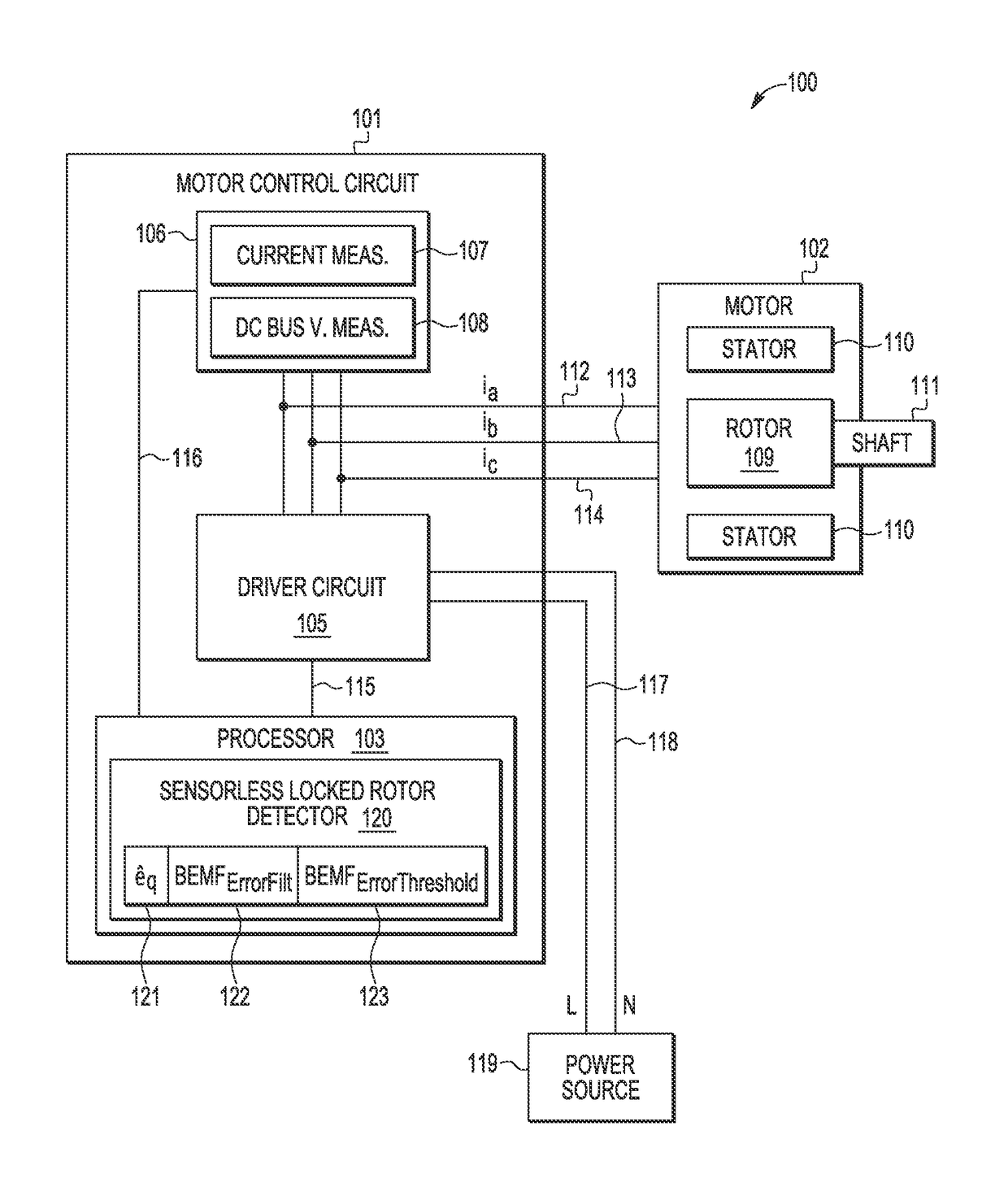
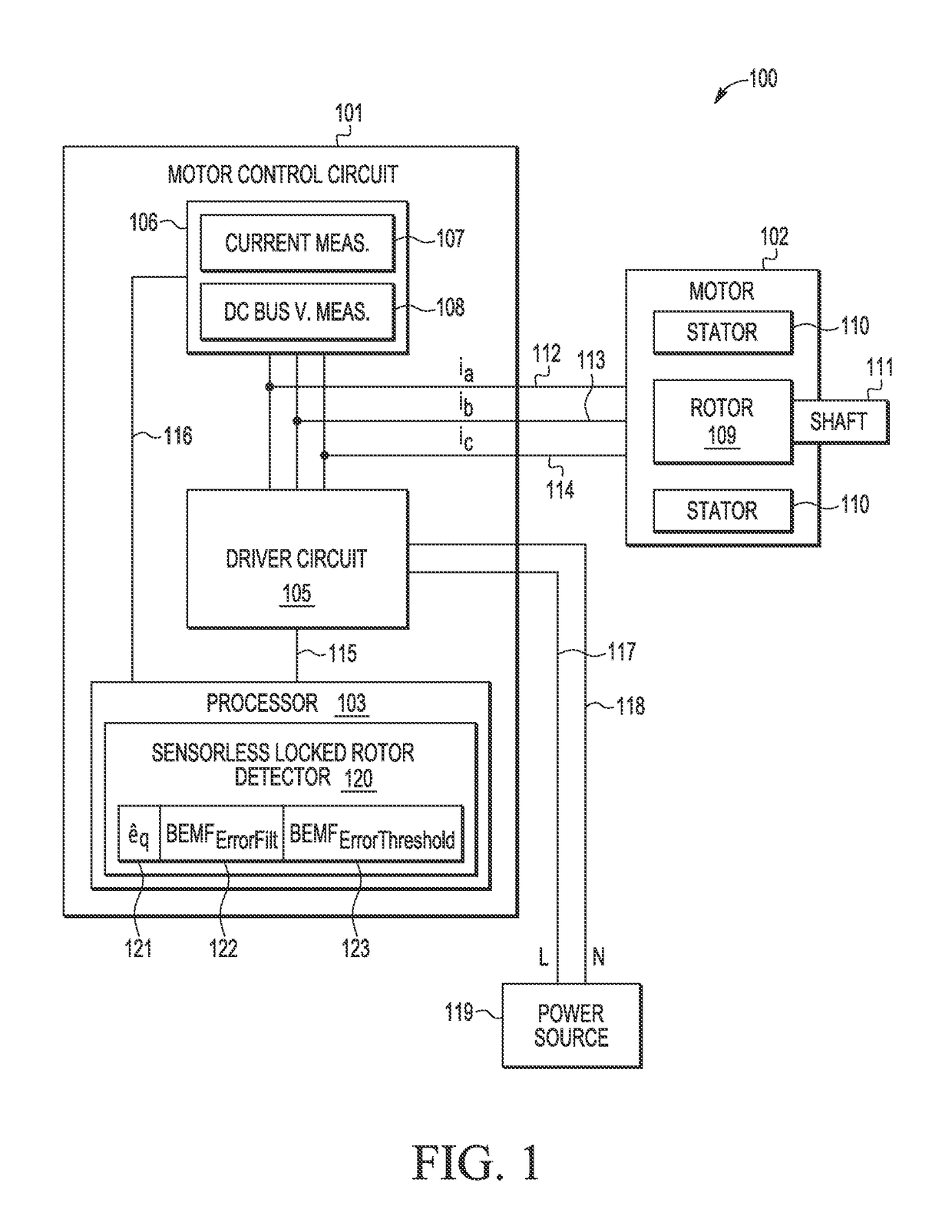
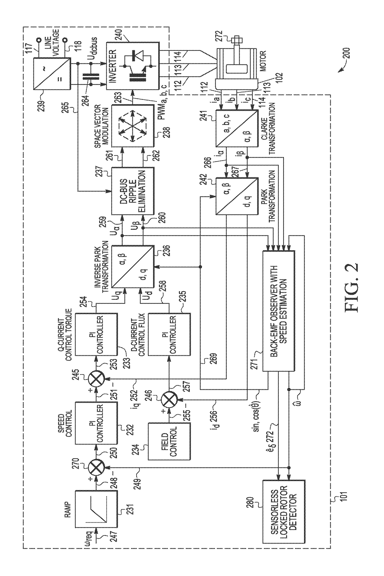
[0015]A sensorless motor control method and apparatus are described for detecting a stalled or locked rotor (a.k.a., motor lock, blocked motor) to reliably and efficiently provide safety protection to address various problems in the art where limitations and disadvantages of conventional solutions and technologies will become apparent to one of skill in the art after reviewing the remainder of the present application with reference to the drawings and detailed description provided herein. In selected embodiments, a software-based method and apparatus are provided for detecting the locked rotor of a permanent magnet synchronous motor (PMSM) by using a BEMF observer system to generate estimated BEMF and speed quantities (e.g., an estimated rotor angular speed value {circumflex over (ω)} and a first estimated BEMF voltage value êδ). Based on the estimated BEMF and speed quantities, a locked rotor fault detector may implement a sensorless field-oriented control algorithm which computes ...


PUM


Abstract

A method and apparatus are provided for detecting a rotor lock condition in a sensorless permanent magnet synchronous motor. A BEMF observer determines an estimated rotor speed {circumflex over (ω)} and a first BEMF voltage value in an estimated rotor-related γ,δ reference frame. In addition, a second estimated BEMF voltage value is calculated in a rotor-related d,q reference frame based on at least a first motor constant and an estimated rotor speed {circumflex over (ω)}. After generating a BEMF error filter value from the first and second estimated BEMF voltage values and calculating a BEMF error threshold value as a function of the estimated rotor speed {circumflex over (ω)} that is subject to a minimum threshold BEMF value, a rotor lock condition is detected based on at least the BEMF error filter value and the BEMF error threshold value.

Description

BACKGROUND OF THE INVENTION[0001]Field of the Invention[0002]The invention relates generally to the field of electric motors. In one aspect, the present invention relates to sensorless permanent magnet synchronous motors (PMSM) and application safety.[0003]Description of the Related Art[0004]Permanent Magnet Synchronous Motors (PMSM) or Brushless DC (BLDC) motors are increasingly popular electric motor design which replaces wear-prone brushed DC motors with an electronic controller that improves the reliability of the unit and reduces the footprint and size, making such PMSM or BLDC motors suitable for applications where space is tight. However, the absence of mechanical or electrical contact between the stator and rotor of the PMSM or BLDC motors presents challenges with determining the relative positions of the component parts. One position-indicating arrangement is to use sensors (e.g., incremental encoders) to detect a motor component position status as part of the motor control...

Claims


Application Information

Patent Timeline
Patent Type & Authority Patents(United States)
IPC IPC(8): H02P6/12H02P6/18H02P29/02H02P29/024
CPCH02P6/12H02P29/0241H02P29/024H02P6/18H02P6/182
Inventor LEPKA, JAROSLAVPROKOP, LIBOR
Owner NXP USA INC
Why Eureka
Try Eureka