
Laser annealing systems and methods with ultra-short dwell times

a technology of laser annealing and dwell time, applied in the field of annealing, can solve the problems of difficult implementation of this type of annealing on patterned wafers, -to-pulse repeatability requirements, image uniformity constraints, etc., and achieve the effect of avoiding adverse speckle effects

Active Publication Date: 2018-09-25
VEECO INSTR
View PDF145 Cites 4 Cited by
  • Summary
  • Abstract
  • Description
  • Claims
  • Application Information

AI Technical Summary

Benefits of technology

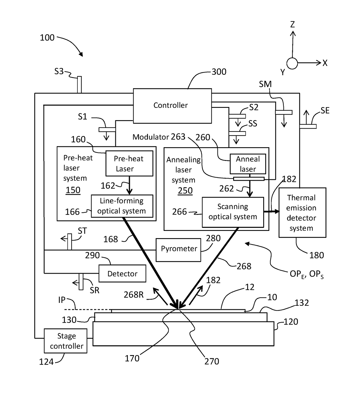
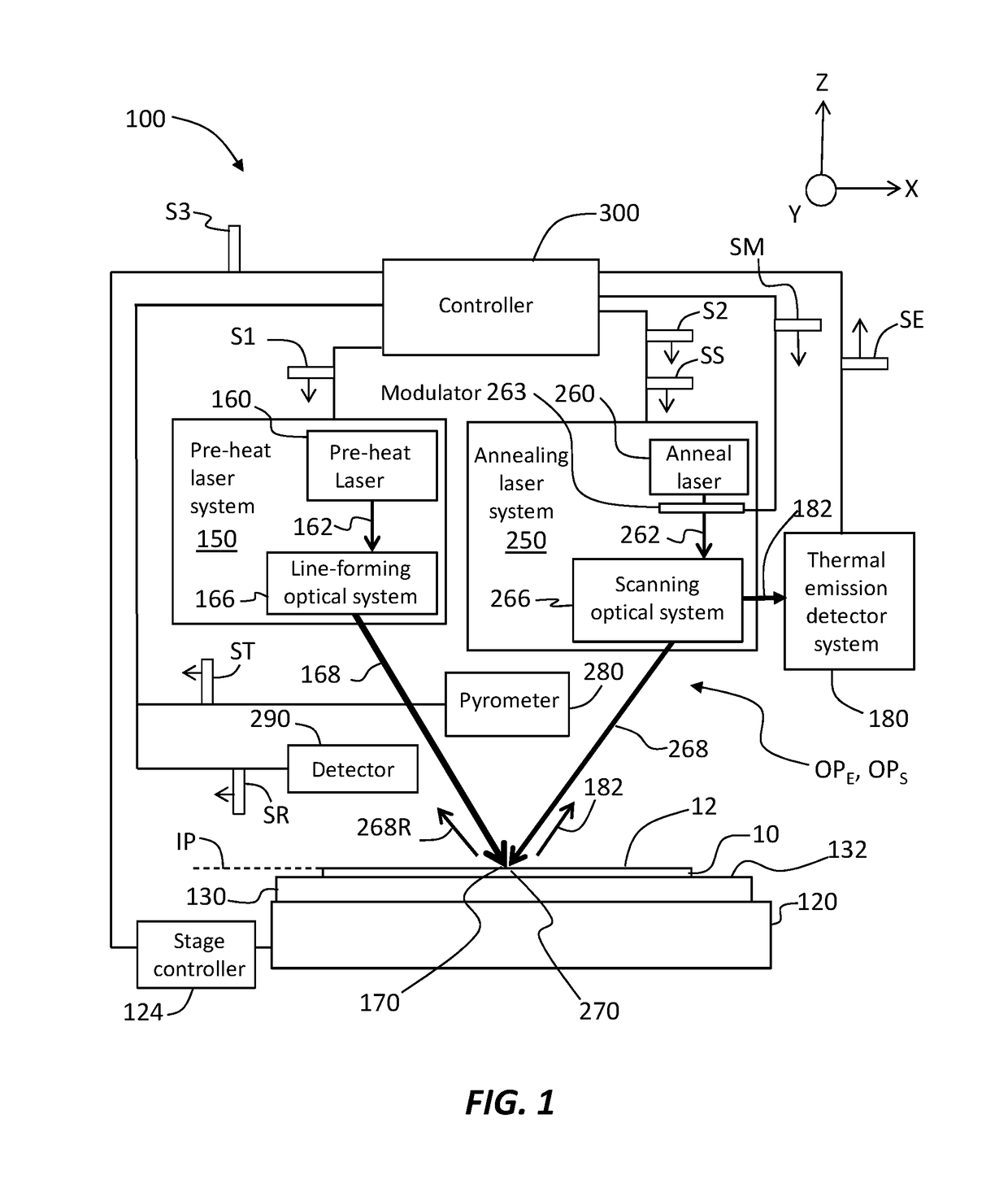
[0007]Laser annealing systems and methods for annealing a wafer with ultra-short dwell times in the range from 10 ns to 500 ns or 25 ns to 250 ns are disclosed. The laser annealing system utilize two laser beams—namely a pre-heat laser beam and a scanning laser beam—that respectively form a pre-heat line image and an annealing image that define a region of overlap. The long dimension L2 of the annealing image runs in the direction of the short dimension W1 of the pre-heat line image. Making L2 substantially larger than W1 (e.g., between 2× and 4× larger) makes it relatively easy to align the pre-heat line image and the annealing image. The pre-heat laser beam is a CW beam that operates in the infrared while the scanning laser beam is either a CW beam or a quasi-CW (QCW) beam. The scanning laser beam scans relative to the pre-heat line image and over the wafer surface sufficiently fast so that the dwell time is in the aforementioned range. These ultra-short dwell times are useful for performing melt annealing of product wafers because they prevent the device structures from reflowing. In an example, the CW and QCW nature of the scanning laser beam avoids the pulse-to-pulse uniformity problems associated with pulsed-based laser annealing systems that rely on just a one or a few light pulses to perform the annealing. In addition, adverse speckle effects are avoided since no substantial beam shaping of the QCW laser beam is required.

Problems solved by technology

In practice, however, it is difficult to implement this type of annealing on patterned wafers due to large temperature non-uniformities that can arise from spatial variations in the optical and thermal properties of the IC chip.
However, this approach suffers from pulse-to-pulse repeatability requirements and pulsed laser image uniformity constraints, and also has a relatively long dwell time in the range of 100 microseconds to 20 milliseconds that exacerbates the above-mentioned issues.
Unfortunately, the power requirements and the dwell time requirements of this approach are far too long to allow for fast recrystalization of the melted substrate.

Method used


Image

  • Laser annealing systems and methods with ultra-short dwell times
  • Laser annealing systems and methods with ultra-short dwell times
  • Laser annealing systems and methods with ultra-short dwell times

Examples


Embodiment Construction

[0042]Reference is now made in detail to various embodiments of the disclosure, examples of which are illustrated in the accompanying drawings. Whenever possible, the same or like reference numbers and symbols are used throughout the drawings to refer to the same or like parts. The drawings are not necessarily to scale, and one skilled in the art will recognize where the drawings have been simplified to illustrate the key aspects of the disclosure. In some of the Figures, Cartesian coordinates are provided for the sake of reference and are not intended as providing limitations on specific directions and orientations of the systems and methods described herein. The claims as set forth below are incorporated into and constitute part of this detailed description.

[0043]In the discussion below, the term “semiconductor substrate” and “wafer” are synonymous and used interchangeably. Likewise, the terms “substrate surface” and “wafer surface” are synonymous and used interchangeably, with “s...


PUM

PropertyMeasurementUnit
length L1aaaaaaaaaa
length L1aaaaaaaaaa
width W2aaaaaaaaaa

Abstract

Laser annealing systems and methods with ultra-short dwell times are disclosed. The method includes locally pre-heating the wafer with a pre-heat line image and then rapidly scanning an annealing image relative to the pre-heat line image to define a scanning overlap region that has a dwell time is in the range from 10 ns to 500 ns. These ultra-short dwell times are useful for performing surface or subsurface melt annealing of product wafers because they prevent the device structures from reflowing.

Description

CROSS-REFERENCE TO RELATED APPLICATIONS[0001]This application claims priority from U.S. Provisional Patent Application Ser. No. 62 / 092,925, filed on Dec. 17, 2014, and which is incorporated by reference herein.FIELD[0002]The present disclosure relates generally to annealing as used in semiconductor manufacturing to fabricate integrated circuits and memory devices, and in particular relates to laser annealing systems and methods with ultra-short dwell times.[0003]Any and all references cited herein are incorporated by reference herein, including: U.S. Pat. Nos. 8,309,474; 8,546,805; 8,865,603; and U.S. patent application Ser. No. 14 / 497,006.BACKGROUND ART[0004]Conventional nanosecond pulsed-laser melt annealing (“conventional melt laser annealing”) offers an ultra-low thermal budget, high dopant activation and super-abrupt junctions that are ideal for advanced integrated circuit (IC) chip fabrication. In practice, however, it is difficult to implement this type of annealing on patter...

Claims


Application Information

Patent Timeline
Patent Type & Authority Patents(United States)
IPC IPC(8): H01L21/324H01L21/67H01L21/268
CPCH01L21/324H01L21/67248H01L21/67115H01L21/268B23K26/00
Inventor HAWRYLUK, ANDREW M.ANIKITCHEV, SERGUEI
Owner VEECO INSTR
Learn More