Water filter cartridge and manifold head seal

a technology of manifold and filter cartridge, which is applied in the direction of filtration separation, separation process, and treatment involving filtration, can solve the problems of leakage testing each filter cartridge, the inability of current filters containing carbon to be tested in this fashion, and the defeat of rapid pressurization

Active Publication Date: 2018-10-02
BAIRD MICAHEL T
View PDF19 Cites 15 Cited by
  • Summary
  • Abstract
  • Description
  • Claims
  • Application Information

AI Technical Summary

Benefits of technology

[0012]A manifold head has a barrel valve into which is inserted a filter cap configured to be placed on the end of a filter cartridge having a housing with a filter element and internal passages configured to convey unfiltered fluid from an inlet passage through the manifold head and filter cap and through the filter element and provide filtered fluid to filter cap at an outlet in fluid communication with an outlet passage through the barrel valve and manifold head. The manifold head, barrel valve and filter cap have a common longitudinal axis preferably extending along a length of the cartridge. The engagement between the manifold head and the filter cap is configured so that the inlet and outlet flow paths through the manifold head, barrel valve and filter cap are in a radial plane. The filter cap is removably inserted into the barrel valve and during filtering use the fluid path between the barrel valve and the filter cap are further contained in a generally cylindrical, annular space that encircles the longitudinal axis of the filter cartridge with a different seal on each end of each annular space. Thus a first flow path in a first radial plane into or out of the filter cap is defined by first and second seals of a first diameter that encircle the longitudinal axis and a second radial flow path in a second radial plane is defined by third and fourth seals of a second diameter that encircle the longitudinal axis. The first and second flow paths are offset axially along the length of the longitudinal axis. The first and second seals have a first diameter and the third and fourth seals have a second diameter, and the first and second diameters may be the same or different. The first flow path may form an inlet or outlet with the second flow path forming an outlet or inlet, respectively. The seals are retained in grooves and are preferably O-ring seals. The resulting seal configuration may avoid creating an axial force that pushes the cartridge away from the manifold head.
[0013]Alternatively described, a first flow path oriented in a first orthogonal plane to the longitudinal axis is located between the first and second seals placed on opposing ends of that first plane, with the first and second seals having the same first diameter. A second fluid flow path oriented in a second orthogonal plane to the longitudinal axis is located between the third and fourth seals on opposing sides of that second plane, with the third and fourth seals having the same second diameter. The first and second seal diameters may be the same or different. The first and second seals have opposing and equal axial forces exerted on them, as do the third and fourth seals. But the opposing forces on each pair of seals result in a net zero axial force. The radial flow located between two opposing seals avoids having the water pressure exert an unbalanced axial force that pushes the cartridge away from the manifold head.
[0014]The filter cartridge on which the filter cap is placed may be held in place with retention mechanisms that require little engagement force, with spring detents and removable snap fits believed suitable. Inclined lugs and locking surfaces may be used to provide a mechanical advantage to engage the seals at the end of the engagement with the manifold head, but the lugs and locking surfaces may be substantially thinner axially and shorter circumferentially than previously used for corresponding filter sizes and water pressures of the prior art. The smaller axial thickness allows a longer filter to be used. The smaller circumferential length allows the cartridges to be engaged more easily and allows large diameter cartridges to be manually engaged with the manifold head. The removal of the force ejecting the cartridge from the manifold head allows larger diameter cartridges and / or flow ports to be used.
[0015]By using two seals encircling the longitudinal axis to define a single flow path, the pressure force on each seal is approximately the same but in an opposing direction and that helps reduce weeping of small amounts of water past the seals. Further, because the seal arrangement and flow arrangement reduces axial force on the filter and filter nozzle, it is possible to leak test each filter cartridge before use. A filter cartridge may be inserted into a test manifold head and pressurized gas, such as air, may be introduced instead of water. The leak rate of gas may be monitored by noting pressure loss, or measuring flow rate needed to maintain a desired pressure. Pressure sensors or flow sensors may be used in connection with vent passages extending through the mating parts to the void volumes between the pairs of seals that define the flow path in order to monitor leakage into the void volumes. After testing is completed the gas pressure may be released and another part tested. The ability to quickly pressurize and depressurize a filter cartridge with air or other gas allows fast relatively inexpensive testing. Current filters that contain carbon cannot be tested in this fashion because the carbon will absorb gas under pressure and will then release the gas slowly and that gas absorption and release defeats the use of rapid pressurization to test for leaks. The use of air or other gas avoids residual water in the filter cartridge and greatly reduces the risk of bacterial growth. The use of vent passages to void volumes allows all areas of the seals to be tested before use. Additionally, the seal testing ability is especially desirable for a filter cartridge having two, spaced apart nozzle seals on the outside of a tubular nozzle where the volume formed between the two seals can be vented to a location outside the manifold head and filter cap, thus allowing gas testing of the sealing effectiveness of the two, spaced apart, nozzle seals. Since more than 1% of filter cartridges may be returned because consumers report the nozzle seals leak usually where the consumer reports poor taste due to bypass of the filter media or that the filter leaks, the ability to test the seal capability before shipment is very desirable. The ability to pressure test the entire filter cartridge and its seals by accessing the various void volumes to check for leaks, allows the entire fluid cartridge to be tested for leaks using gas or liquid, but preferably using a gas such as air.
[0016]Further, by providing vent passages to the void areas, it becomes possible to not only test that the filter cartridge itself is sealed but it becomes possible to test that the internal filter media is sealed to ensure that there is no bypass of the internal filter media. It is not possible to test for this condition in other current filter configurations unless destructive testing of the filter is performed.

Problems solved by technology

Further, because the seal arrangement and flow arrangement reduces axial force on the filter and filter nozzle, it is possible to leak test each filter cartridge before use.
Current filters that contain carbon cannot be tested in this fashion because the carbon will absorb gas under pressure and will then release the gas slowly and that gas absorption and release defeats the use of rapid pressurization to test for leaks.

Method used


Image

  • Water filter cartridge and manifold head seal
  • Water filter cartridge and manifold head seal
  • Water filter cartridge and manifold head seal

Examples


Embodiment Construction

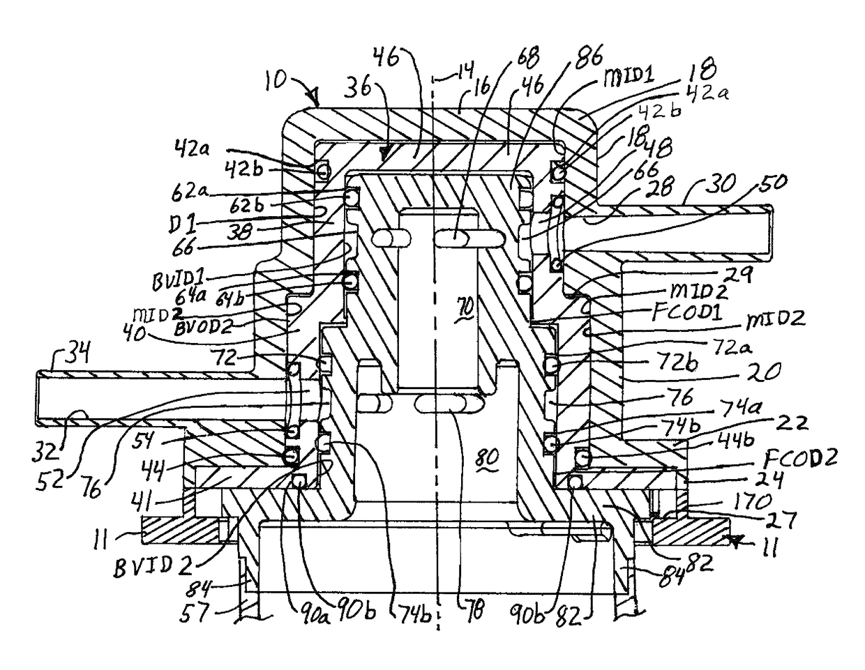
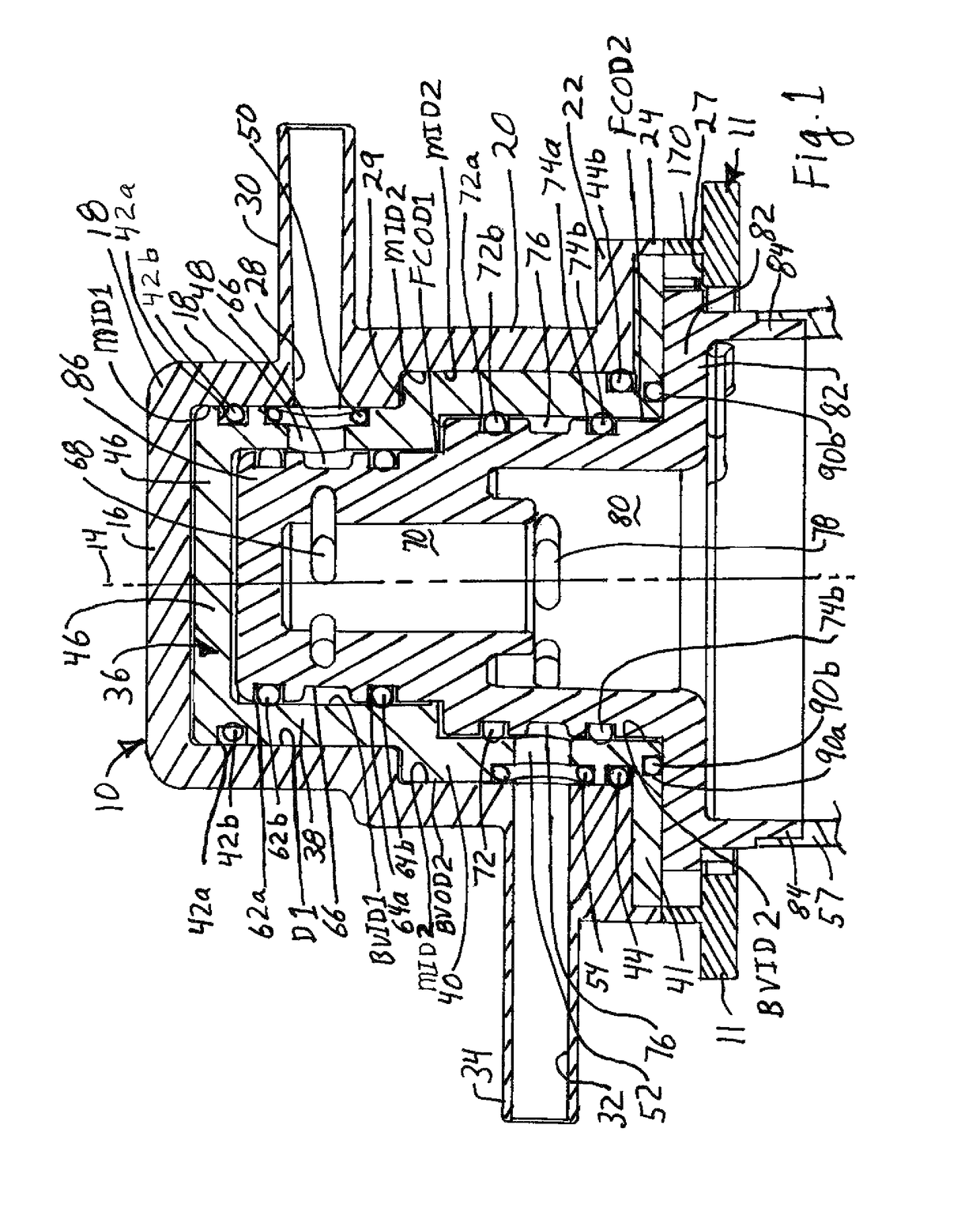
[0072]Referring to FIGS. 1-3, 6-7 and 11-12, a filter manifold head 10 is connected to a manifold base 11. The manifold head 10 has a sidewall 12 (FIGS. 11-12) encircling longitudinal axis 14 and connected to end wall 16 to close one end of the manifold head and form a hollow interior with an opening opposite end wall 16. The sidewall 12 may have a first generally cylindrical portion 18 adjacent the end wall 16 and having a first interior diameter MID1 (Manifold Inner Diameter 1). The sidewall 12 may have a second portion 20 adjoining the first portion and closer to the open end of the manifold head with the second portion 20 having a second interior diameter MID2 (Manifold Inner Diameter 2). Advantageously MID2 is greater than MID1 and the end wall 16 is orthogonal to the longitudinal axis 14. Advantageously an outwardly extending mounting flange 22 encircles at least part of and preferably the entire open end of the manifold head 10. The mounting flange 22 advantageously has a ski...


PUM

PropertyMeasurementUnit
pressureaaaaaaaaaa
diameteraaaaaaaaaa
diameteraaaaaaaaaa

Abstract

A water filter cartridge has a cap with radially oriented first and second (either inlet or outlet) flow channels on first and second generally cylindrical portions. First and second seals encircle the first flow channel on the first portion and third and fourth seals encircle the second flow channel on the second portion. The second and third seals form a void volume during use which may be accessed by a vent path to eliminate moisture or to test for or indicate leaks. The radial flow paths reduce axial, push out forces on the filter cartridge and allow smaller locking tabs to be used. The first seal forms a top void volume during use which may be accessed by a vent path to eliminate moisture or to test for or indicate leaks.

Description

CROSS-REFERENCE TO RELATED APPLICATIONS[0001]The application claims the benefit under 35 U.S.C. § 119(e) to Provisional Patent Application No. 61 / 983,392 filed Apr. 23, 2014 and Provisional Patent Application No. 62 / 020,218 filed Jul. 2, 2014 the entire contents of which are incorporated herein by reference.BACKGROUND[0002]The present invention relates generally to water filter cartridges used in home and business water filter systems, and optionally used in commercial applications. Current filter systems have a manifold head with a manifold head inlet port connected to a source of water and a manifold head outlet port connected to a dispenser for the filtered water, such as a household refrigerator, or an apparatus using filtered water such as a coffee maker. The manifold head typically has a generally cylindrical, cup shaped interior, and often has a single, uniform diameter or two different diameters forming a stepped configuration. A removable filter cartridge has a cartridge he...

Claims


Application Information

Patent Timeline
Patent Type & Authority Patents(United States)
IPC IPC(8): C02F1/00B01D35/30G01M3/04G01M3/26C02F103/02
CPCC02F1/003B01D35/30G01M3/04G01M3/26C02F2307/10C02F2103/02C02F2201/004C02F2201/005C02F2201/006B01D2201/301
Inventor BAIRD, MICHAEL T.PARMLEY, RANDY L.JULOS, JOHN J.
Owner BAIRD MICAHEL T
Why Eureka
Try Eureka