Thermo-gravimetric apparatus

a gravity measurement and thermometer technology, applied in the field of thermometers, can solve the problems of insufficient indirect heating of heat conducting members, inability to visually observe the changes of samples being studied by thermal analysis, and poor measurement accuracy, so as to improve the measurement accuracy of thermal analysis

Active Publication Date: 2018-10-02
HITACHI HIGH TECH SCI CORP
View PDF30 Cites 0 Cited by
  • Summary
  • Abstract
  • Description
  • Claims
  • Application Information

AI Technical Summary

Benefits of technology

[0013]The present invention has been made in view of the above-described circumstances, and one of objects of the present invention is to provide a thermal analyzer that can be used to observe a sample with a furnace tube as changes occur in the sample in a thermal analysis, and with which the measurement accuracy of thermal analysis can be improved through the reduction of the radiation heat that directly radiates from a heating furnace onto the sample inside the furnace tube.

Problems solved by technology

While the foregoing thermal analyzer can be used to detect the required thermophysical properties, changes in the sample being studied by thermal analysis cannot be visually observed.
However, such indirect heating with the heat conducting member may not be sufficient to meet the requirement for observing a sample at high temperatures above 500° C. in a thermal analysis.
Such changes in radiation heat are reflected in the differential heat signal, and the measurement accuracy suffers.

Method used


Image

  • Thermo-gravimetric apparatus
  • Thermo-gravimetric apparatus
  • Thermo-gravimetric apparatus

Examples


Embodiment Construction

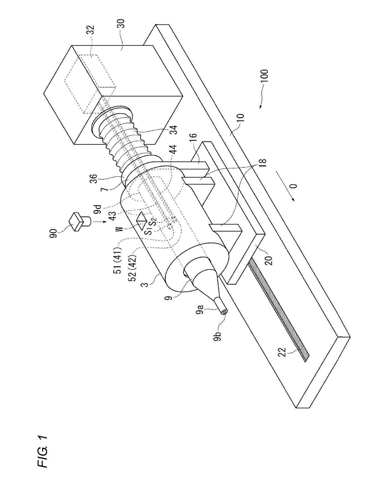
[0026]An embodiment of the present invention is described below with reference to the accompanying drawings. In the following, the term “anterior end (side)” will be used to refer to the anterior end portion 9a side of a furnace tube 9 in a direction along axial direction O, and the term “posterior end (side)” will be used to refer to the opposite side of the furnace tube 9.

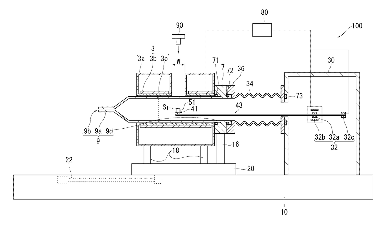
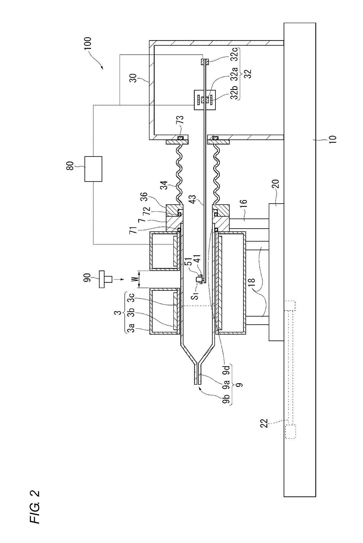
[0027]FIG. 1 is a perspective view of a configuration of a thermal analyzer 100 according to the embodiment of the present invention. FIG. 2 is a cross sectional view of the thermal analyzer 100 taken in a vertical section that passes an axis of the furnace tube 9.

[0028]The thermal analyzer 100 is configured as a Thermogravimetric (TG) apparatus, and is provided with: a cylindrical furnace tube 9; a cylindrical heating furnace 3 surrounding the furnace tube 9 from outside; a pair of sample holders 41 and 42 arranged inside the furnace tube 9; a support base 20; a measurement chamber 30 connected to a posterior en...


PUM

PropertyMeasurementUnit
sizeaaaaaaaaaa
sizeaaaaaaaaaa
temperaturesaaaaaaaaaa

Abstract

A thermal analyzer is provided with: a furnace tube; a pair of sample holders; a heating furnace; a measurement chamber; and a measurement unit arranged inside the measurement chamber. The sample holders are arranged inside the furnace tube and are provided with mounting faces on which a pair of sample containers are mounted respectively. The heating furnace has an opening through which a measurement sample is observable, the opening being located at a position above the center of a virtual segment which connects centers of gravity of the mounting faces of the sample holders. The opening is formed to have a size, as viewed in a direction perpendicular to the axial direction and the mounting faces, of 7 mm or more in the direction along the virtual segment and of 3 mm or more in the direction perpendicular to the virtual segment.

Description

CROSS-REFERENCE TO RELATED APPLICATION[0001]This application claims priority from Japanese Patent Application No. 2013-251101, filed on Dec. 4, 2013, the entire subject matter of which is incorporated herein by reference.BACKGROUND[0002]1. Technical Field[0003]The present invention relates to a thermal analyzer for measuring a physical change of a sample along with its temperature change caused by heating the sample.[0004]2. Description of the Related Art[0005]Conventionally, as a technique of evaluating temperature characteristics of a sample, there has been employed a technique called thermal analysis for measuring a physical change of a sample along with its temperature change caused by heating the sample. A definition of thermal analysis can be found in JIS K 0129: 2005 “General rules for thermal analysis,” and thermal analysis, according to this definition, includes all techniques that measure the physical properties of a measurement target (sample) under program controlled tem...

Claims


Application Information

Patent Timeline
Patent Type & Authority Patents(United States)
IPC IPC(8): G01N5/04G01N25/00G01N5/00
CPCG01N5/00
Inventor NISHIMURA, SHINYAYAMADA, KENTARONAGASAWA, KANJITAKASAWA, RYOJI
Owner HITACHI HIGH TECH SCI CORP
Why Eureka
Try Eureka