Devices and methods for measuring thermal flux and estimating rate of change of reactive material within a subsurface formation

a technology of thermal flux and reactive material, which is applied in the direction of instruments, surveying, borehole/well accessories, etc., can solve the problems of difficult identification and cleanup of source zones, difficult locating regions within source zones that require treatment, and sparse distribution of reactive materials

Active Publication Date: 2018-10-09
GSI ENVIRONMENTAL +1
View PDF24 Cites 4 Cited by
  • Summary
  • Abstract
  • Description
  • Claims
  • Application Information

AI Technical Summary

Problems solved by technology

An ongoing environmental challenge is managing the legacy of anthropogenic activities that have resulted in the contamination of groundwater, surface water, soil, and / or soil gas via subsurface source zones.
The identification and cleanup of source zones may be difficult due to heterogeneity within the subsurface formations in the form of spatial variations in permeability and porosity that may result in the sparse distribution of the reactive materials within the subsurface formations.
As a result, locating regions within source zones that require treatment is difficult.
Furthermore, monitoring the reactive materials within source zones and the effect of remedial agents on reactive materials within source zones is challenging due to the relative inaccessibility of these subsurface formations, which may extend well over about 30 feet below ground surface.
The monitoring of reactive materials introduced into preexisting subsurface formations poses an ongoing challenge for the environmental management of various industrial facilities as well as waste collection, processing, and storage facilities.
These CO2-based methods provide estimates based on a small area over a short period of time, but are less effective at providing the long-term monitoring capability needed to assess ongoing contamination events or to assess the effectiveness of remediation of the contaminated subsurface formation.
Chimneying, ground surface cover, heterogeneities in the soil, and short or long term climatic events may cause a large variability in reactive material loss rates estimated using these existing methods.
Further, inorganic reactive materials, such as aluminum, may not be compatible with these existing methods because the degradation reactions within the contaminated subsurface formations may not produce CO2.

Method used


Image

  • Devices and methods for measuring thermal flux and estimating rate of change of reactive material within a subsurface formation
  • Devices and methods for measuring thermal flux and estimating rate of change of reactive material within a subsurface formation
  • Devices and methods for measuring thermal flux and estimating rate of change of reactive material within a subsurface formation

Examples


example 1

g of Rate of Change of LNAPL Reactive Materials Within a Subsurface Formation Using Subsurface Temperature Measurements

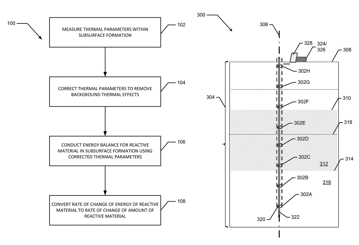
[0102]To demonstrate the monitoring of the rate of change of a reactive material within a subsurface formation using the methods described herein above, the following experiments were conducted. Five 37-foot long PVC rods with eight attached thermocouples similar to the corresponding elements of the subsurface thermal monitoring system 300 illustrated in FIG. 4 were installed within a subsurface formation known to contain LNAPL regions at the locations N1, N2, N3, N4, and B1 as illustrated in FIG. 4. These subsurface assemblies of thermocouples, referred to as “sticks”, were located in an east-west transect across the northern edge of the site. The first three locations in the transect (N1-N3) were known to contain LNAPL regions. The southernmost location (B1) was considered to be a background location, where subsurface temperatures are not affected by LNAPL.

[0103]E...


PUM

PropertyMeasurementUnit
depthaaaaaaaaaa
thermal monitoringaaaaaaaaaa
thermal parameteraaaaaaaaaa

Abstract

Devices and methods for measuring subsurface thermal fluxes and for estimating a rate of change in the amount of a reactive material within a subsurface formation using the measured thermal fluxes are described herein. The methods of measuring subsurface thermal fluxes may use at least one array of temperature sensors distributed along a vertical transect projecting from the surface and into the subsurface of a region of interest. Methods of estimating a rate of change in the amount of a reactive material within a portion of the region of interest based on perturbations of the thermal profile within the subsurface due to an endothermic or exothermic degradation of the reactive material within the portion of the region of interest are also described herein.

Description

CROSS REFERENCE TO RELATED APPLICATION[0001]This application claims priority from U.S. provisional patent application Ser. No. 61 / 941,194, entitled “Subsurface Thermal Flux Tools” filed on Feb. 18, 2014, the entirety of which is incorporated by reference herein.FIELD OF THE INVENTION[0002]This application relates to devices and methods for measuring subsurface thermal fluxes and for estimating rates of changes of the amount of reactive material within a subsurface formation using the measured thermal fluxes. In particular, this application relates to methods of measuring subsurface thermal fluxes using at least one array of temperature sensors distributed along a vertical transect extending from the surface and into the subsurface of a region of interest. This application further relates to methods of estimating a rate of change in an amount of a reactive material within a portion of the region of interest based on perturbations of the thermal profile within the subsurface due to an...

Claims


Application Information

Patent Timeline
Patent Type & Authority Patents(United States)
IPC IPC(8): G01K1/02G01V9/00G01K17/08E21B47/06
CPCG01K17/08G01V9/005G01K1/026E21B47/065E21B47/07
Inventor SALE, THOMAS C.STOCKWELL, EMILY B.NEWELL, CHARLES J.KULKARNI, POONAM R.
Owner GSI ENVIRONMENTAL
Why Eureka
Try Eureka