Multi-core cable and production method therefor
a multi-core cable and production method technology, applied in the field of multi-core cables, can solve the problems of signal quality deterioration, signal strength decline, crosstalk increase, etc., and achieve the effect of low probability of transmission performan
- Summary
- Abstract
- Description
- Claims
- Application Information
AI Technical Summary
Benefits of technology
Problems solved by technology
Method used
Image

Examples
example 1
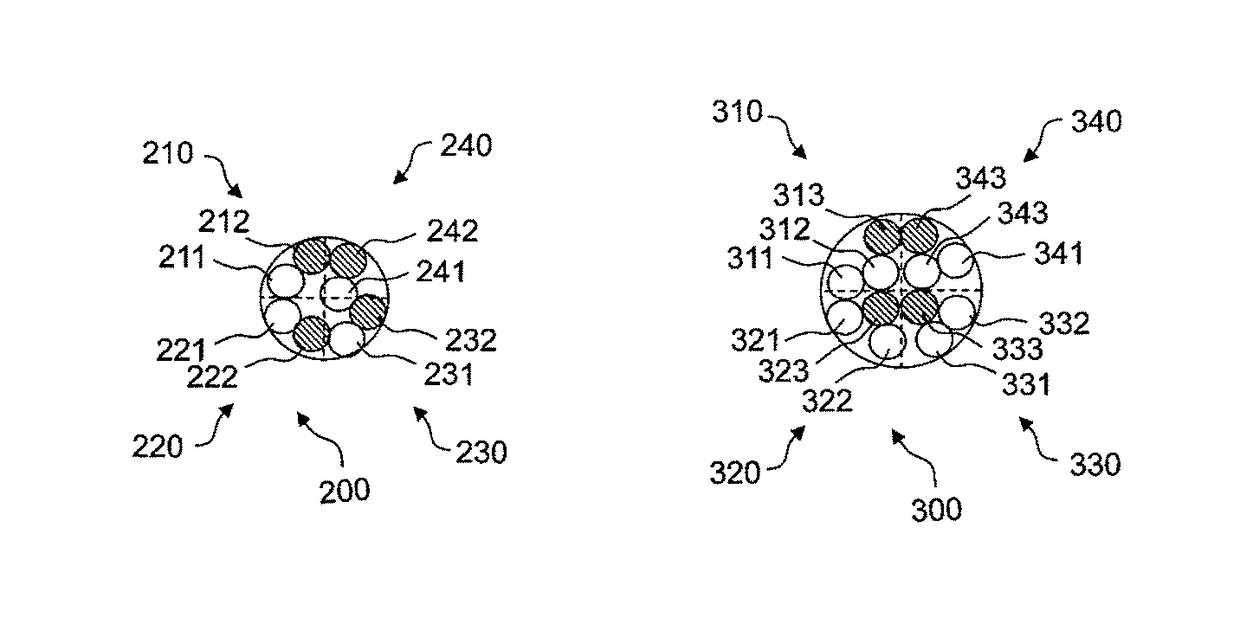
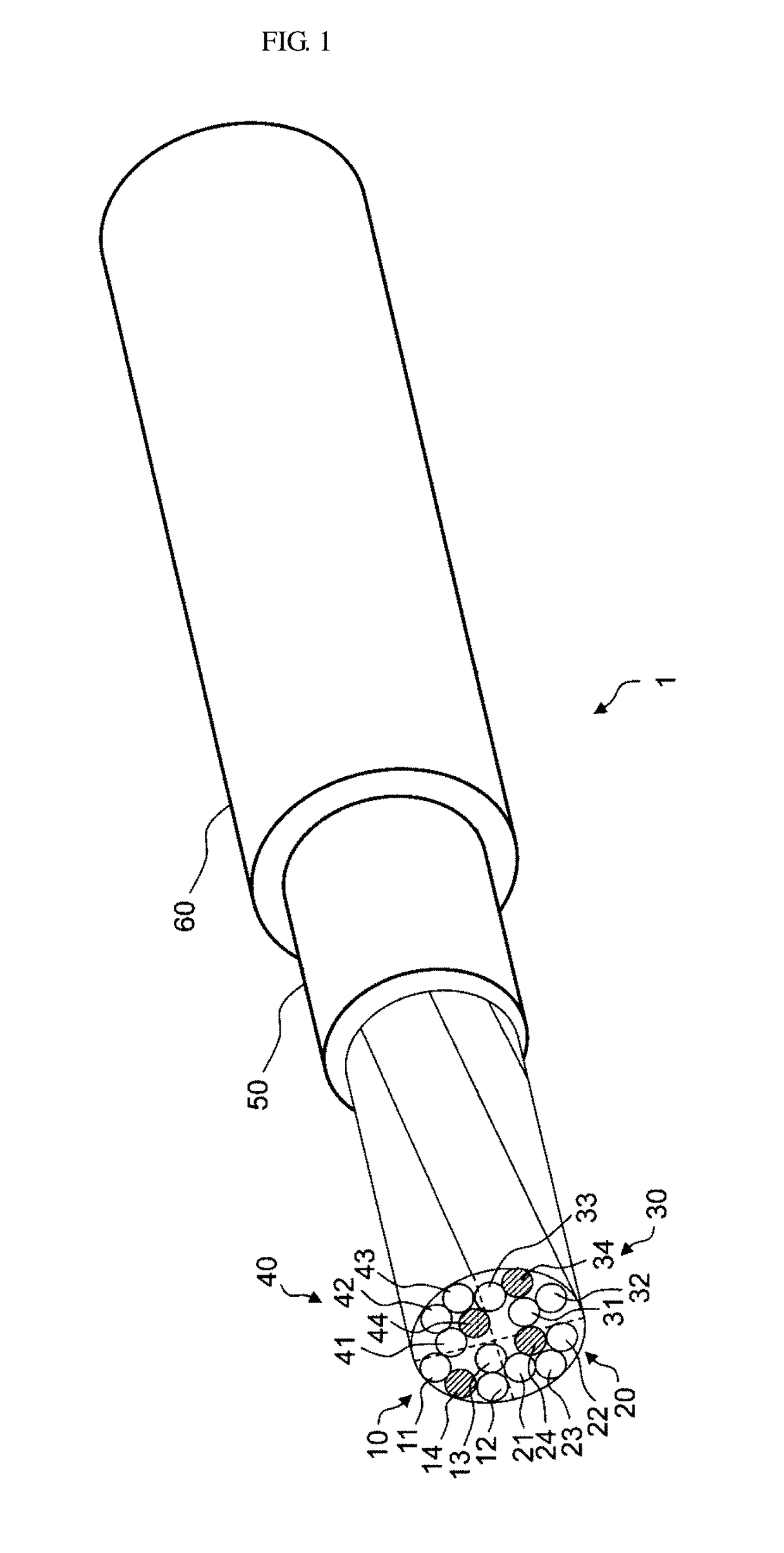
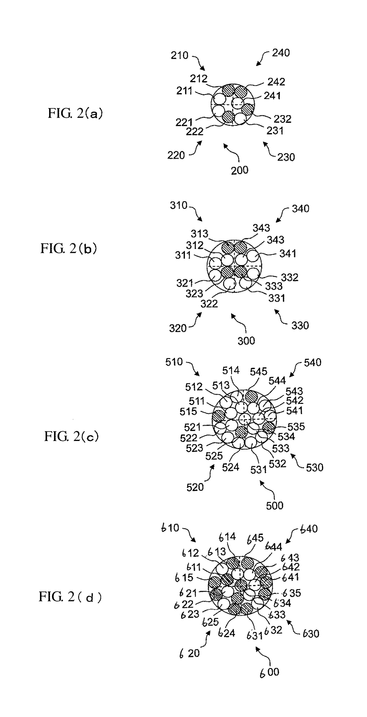
[0084]Next, crosstalks of eight cables of a comparative example, a first example, a second example, a third example, a fourth example, a fifth example, a sixth example, and a seventh example were compared. Cores thereof were formed in three levels of four conductor bundles, four conductor groups, and a core. For the cables, in the comparative example and the first example, four conductor bundles were each formed by small-twisting four insulated conductors and one non-insulated conductor. In the second example, four conductor bundles were each formed by small-twisting four insulated conductors and two non-insulated conductors. In the third and sixth examples, four conductor bundles were each formed by small-twisting two insulated conductors and three non-insulated conductors. In the fourth, fifth, and seventh examples, four conductor bundles were each formed by small-twisting four insulated conductors and six non-insulated conductors.
[0085]In addition, the four conductor groups were ...
example 2
[0100]Next, crosstalks when the ratio between the number of non-insulated conductors and the number of insulated conductors was changed were compared. Here, the ratio between the number of non-insulated conductors and the number of insulated conductors was changed to 0:16, 1:16, 1:8 (2:16), 1:4 (4:16), 1:3 (6:18), 1:2 (8:16), and 1:1 (16:16). Here, the numbers in the parentheses indicate the ratio between the number of non-insulated conductors and the number of insulated conductors when the number of insulators was uniformly 16. Here, the size of a core material of the insulated conductor was 42AWG and the size of the non-insulated conductor was 38AWG.
[0101]FIG. 12 is a graph showing a change in crosstalk when the ratio between the number of insulated conductors and the number of non-insulated conductors included in the cable was changed if a signal has a frequency of 20 (MHz). In FIG. 12, the horizontal axis represents the ratio between the number of insulated conductors and the nu...
example 3
[0105]Next, characteristic impedances and losses when a value obtained by dividing a distance from the center of an insulated conductor to the surface of an adjacent non-insulated conductor by a distance from the center of the insulated conductor to the outermost surface of the insulated conductor was changed were compared. Table 6 show changes in characteristic impedance (Zo) and loss when a value obtained by dividing a distance (L) from the center of an insulated conductor to the surface of an adjacent non-insulated conductor by a distance (l) from the center of the insulated conductor to the outermost surface of the insulated conductor was changed. Here, when (L / l) was 1, this indicated that the non-insulated conductor and the insulated conductor were in contact with each other. When (L / l) was 2, this indicated that a distance between the non-insulated conductor and the insulated conductor was twice a distance from the center of the insulated conductor to the outermost surface of...
PUM
| Property | Measurement | Unit |
|---|---|---|
| frequency | aaaaa | aaaaa |
| length | aaaaa | aaaaa |
| length | aaaaa | aaaaa |
Abstract
Description
Claims
Application Information