KD chair and stool construction

a technology for chairs and stools, applied in the field of furniture, can solve the problems of severing the limits of how sophisticated products can be designed, time spent assembling and the difficulty of assembling units, and reducing the cubic measure of chairs, so as to reduce transportation, warehouse storage, handling and inventory costs, and simplify the effect of assembly

Active Publication Date: 2018-10-16
REGIT HLDG LLC
View PDF38 Cites 2 Cited by
  • Summary
  • Abstract
  • Description
  • Claims
  • Application Information

AI Technical Summary

Benefits of technology

[0024]This invention provides for a unique construction for chairs both upholstered and non-upholstered utilizing factory manufactured sub-assemblies, the ability to nest one sub-assembly within another, metal rods, bolts, and removable chair back and seat covers which in combination reduce the cubic measure of the chair once packaged for reduced transportation, warehouse storage, handling and inventory costs; simplified and reduced assembly times while yielding a stronger and sturdier unit. The construction is ideal for, but not limited to, dining, accent and slipper chairs; bar and counter stools or any chair which is constructed with a 4 sided seat box construction. Removable covers can be made of woven and non-woven fabric, leather, PVC or any pliable material which can be sewn into the corresponding back and seat covers. In the preferred embodiment each chair consists of a factory assembled arched-legged or straight-legged chair back sub-assembly consisting of two (2) full length arched or straight legs permanently connected together with a determined number of cross rails based on each chairs height with the upper back support section of solid material such as wood or metal for non-upholstered chairs or wrapped with upholstery foam and upholstered in a protective permanently attached fabric ready to accept the back cover for upholstered chairs; a front factory assembled front leg sub-assembly consisting of the 2 chair front legs with a permanently attached cross rail connected to the top portion of each leg; a factory assembled 3 sided seat box sub-assembly with upholstery foam covered with a protective permanently attached fabric prepared to accept the seat cover; a left and right horizontal side rail machined to the correct length as determined by each chair's specifications and machined to accept the front and arched or straight back leg sub-assemblies; two (2) metal attaching bolts, nested within a rabbet machined longitudinally within the side rail and a metal hex socket T-nut and knurled nut securing the front leg assembly to the back leg assembly; and a fitted chair back and chair seat cover to complete the assembly of the embodied invention. Because of the superior tensile strength of the metal bolts over common wood used in chair constructions, this invention is significantly stronger.
[0025]The chair construction is manufactured so that the upholstered top portion of said arched back leg assembly nests within said 3 sided seat assembly significantly reducing the height of the packing carton which reduces the cubic size of packaging increasing the unit load factor in any shipping container and reducing freight costs.
[0026]The said fitted covers described above are quickly and easily slid over the factory installed protective material and Velcro's easily in place. Because the covers are easily attached and removed, said covers can be conveniently cleaned. Covers can be sold separately so that retailers can stock one chair and sell an infinite number of covers saving warehouse space, reducing inventory costs and reduced shelf space maximizing store sales per square foot. Covers can be mixed and matched. For example, two (2) cover sets (each set contains a back cover and seat cover) can give consumers 4 cover options.
[0027]The embodiment of this invention because of said factory pre-assemblies reduces the number of individual parts. The resulting embodiment is a stronger, more rigid construction eliminating racking and loosens joints. In the event said embodiment ever loosens, removing the 2 bolts securing the seat box and removing said seat box exposes the 2 securing hex socket T-nuts. Because of the pre-assemblies, tightening the 2 securing nuts returns said embodiment to its original strength and solidity.

Problems solved by technology

A key resistance to ready-to assemble furniture is the time spent assembling and the difficulty in assembling units as well as the confusion often caused by poorly written instructions.
Although this puts sever limits on how sophisticated products can be designed, in the consumers' eyes it is time saving and simple to assemble.
Fewer parts also means fewer joints (which can loosen over time) leading to sturdier, more stable units once assembled.
Because of the large number of parts individually connected to one another, a large number of joints are created, generating more points of weakness within the structure.
In using wood dowels and wood nuts referred to as “rod caps,” only a limited amount of torque is able to be applied to secure each connection.
With such a large number of individual parts, units constructed using the Alster system also take a significant amount of time to assemble which consumers see as a negative feature.
It also is a time consuming chore to retighten all of these joints.
Additionally, U.S. Pat. No. 719,837 to Morton; U.S. Pat. No. 1,813,072 to Murdock; U.S. Pat. No. 4,261,667 to Ervin et al., the use of individual and separate parts and not sub-assemblies and the inability to apply sufficient torque, and in some cases, no torque at all, will, over time, generate weaker joints.
A common weakness in all of these systems, therefore, is the number of joints created using such a large number of individual parts.
Without being able to generate enough torque during assembly the joints cannot be made sufficiently rigid to withstand normal wear and tear without racking.
Nor is there a way to quickly retighten each individual part at each joint when joints do loosen—a natural occurrence when the units are used as envisaged.
The joint based on a wood screw made of metal into a wood part, particularly in a rocking chair as shown in FIG. 3 of Prince et al., will quickly lose much of its holding power and, in all likelihood, strip out if tightened too aggressively.
In U.S. Pat. No. 233,478 to Creager, a back leg and front leg assembly is envisioned, but weaknesses are again created with the number of joints and lack, in this case, of any torque being applied to create a strong rigid connection resistant to racking.

Method used


Image

  • KD chair and stool construction
  • KD chair and stool construction
  • KD chair and stool construction

Examples


Embodiment Construction

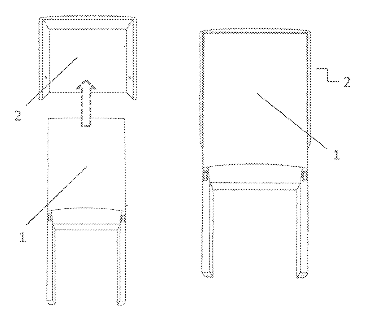
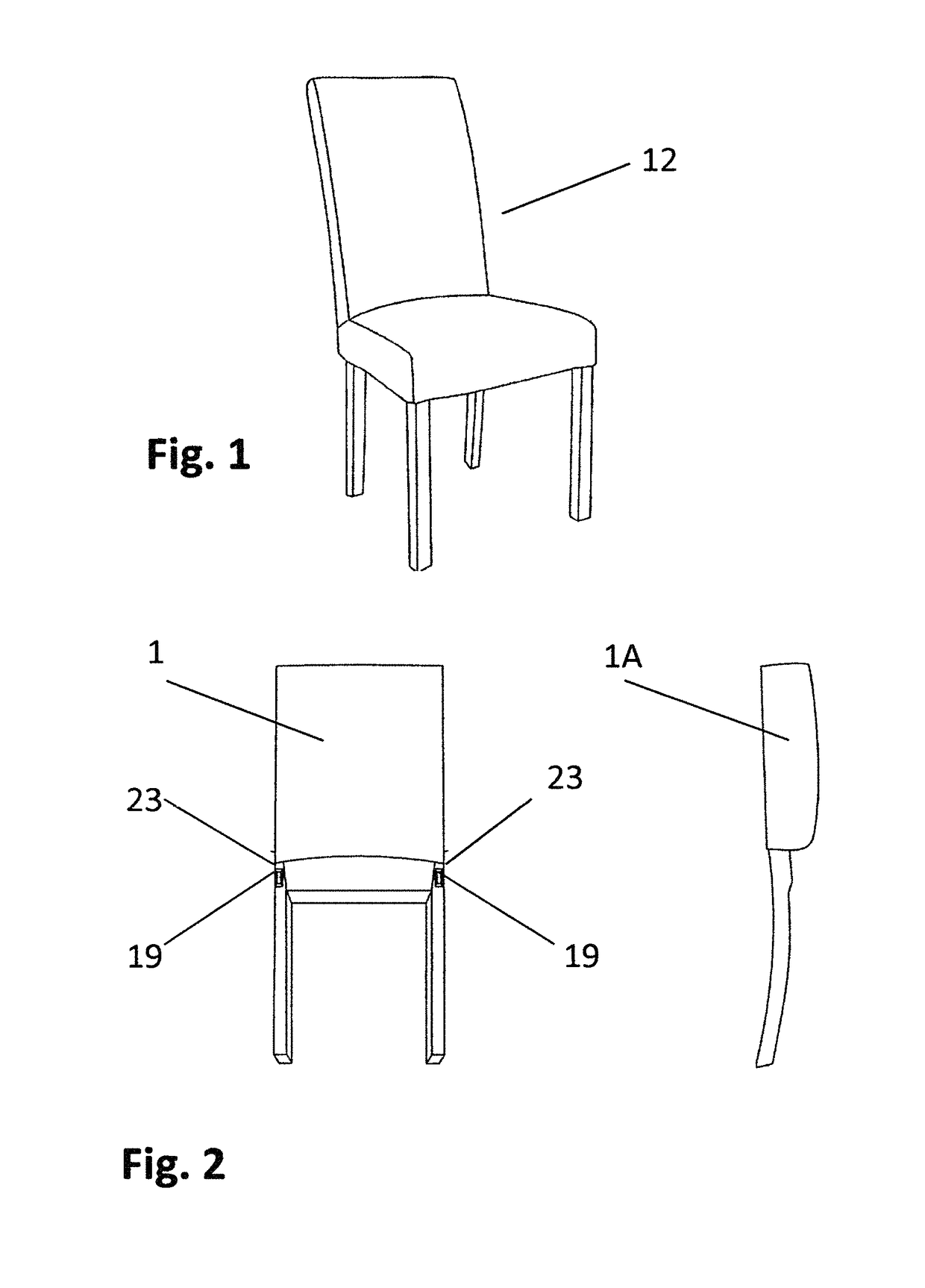
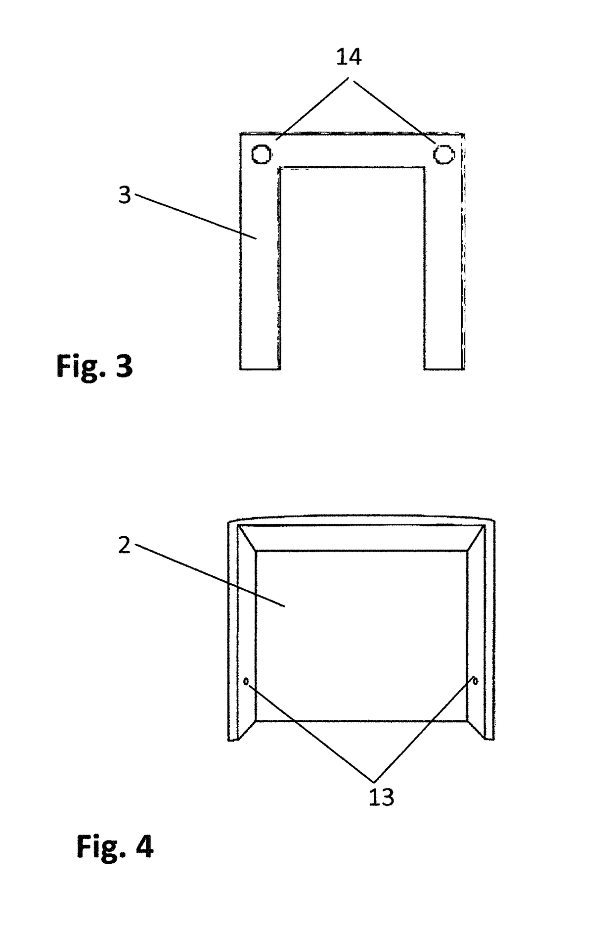
[0038]FIG. 1 shows the final assembled preferred embodiment of a ready-to-assemble chair 12 of the present invention. The chair is composed of three (3) sub-assemblies: the factory assembled back sub-assembly, FIG. 2, (1, 1A); the factory assembled front leg sub-assembly, FIG. 3, (3); and the factory assembled seat box sub-assembly, FIG. 4, (2). The preassembled back assembly 1 consists of a determined number of structural and / or ornamental cross rails (e.g., 18), a mortise 19 on the interior of each leg of the assembly with a knurled nut 23 inserted within the mortise 19 to receive the threaded end 22 of the metal attaching rod 7. The front leg sub-assembly consists of the two front legs and a top cross rail existing on the same plane and assembled in a horseshoe shape. The left and right top corners have a hole 14 bored through, through which the attaching rod 7 is to be fed to attach the back leg sub-assembly to the front leg sub-assembly. Washer 10 and hex socket T-nut 8 will be...


PUM


Abstract

A ready-to-assemble upholstered and non-upholstered chair consisting of factory assembled sub-assemblies reducing the number of overall parts and assembly hardware which decreases the packaged cubic measure allowing more units to be loaded into shipping containers and trailers, inventoried in warehouses and distribution centers and displayed in retail outlets thereby reducing transportation and handling costs, while simplifying and expediting the assembly process. The invention includes a seat box sub-assembly so constructed to allow a portion of the chair back leg sub-assembly to nest therein reducing the package profile and cubic measure, as well as a front leg sub-assembly. The front leg and back leg sub-assemblies are assembled utilizing a left and right tenoned side rail which inserts into mortises on the front and back leg assemblies. The leg sub-assemblies are secured with a metal bolt, threaded on each end, housed longitudinally within a routed channel running on the exterior face of each side rail. The bolt is secured by threading one end into the pre-installed knurled nut in the back leg sub-assembly and a hex socket T-nut and washer on the face of the front leg sub-assembly. The seat box sub-assembly is fitted over the front leg sub-assembly and the left and right side rails and secured on the underside with metal bolts. With the factory manufactured pre-assemblies resulting in fewer joints, the assembled chair is stronger eliminating potential racking. On upholstered chairs, the removable outer decorative back and seat cover are positioned over the chair back and chair seat and quickly Velcro's into place. Chair covers can be removed for cleaning or retailers can sell additional covers in a variety of materials and designs without needing to stock additional chairs. Once assembled, the invention offers the distinction that no assembly hardware is visible, giving the chair a “factory made” look.

Description

CROSS REFERENCE TO RELATED APPLICATION[0001]This application claims priority to U.S. Provisional Patent Application No. 62 / 116,097, filed Feb. 13, 2015, the entire content of which is incorporated herein by reference.STATEMENT REGARDING FEDERALLY SPONSORED RESEARCH OR DEVELOPMENT[0002]Not applicableFIELD OF THE INVENTION[0003]The present invention relates to the field of furniture, particularly ready-to-assemble chairs with sub-assemblies which reduces the total number of components and a single linear threaded attaching rod which results in a stronger, more stable, quicker and simpler assembly and disassembly and configured in such a way that in their dissembled state can be packaged in a carton so as to reduce cubic measure thereby reducing transportation, handling and storage costs.BACKGROUND OF THE INVENTION[0004]Ready-to-assemble furniture continues to grow in popularity. The number of retail outlets selling ready-to-assemble furniture continues to grow both domestically and in...

Claims


Application Information

Patent Timeline
Patent Type & Authority Patents(United States)
IPC IPC(8): A47C4/02A47C4/03F16B12/14
CPCA47C4/028A47C4/03A47C4/024F16B12/14
Inventor YAO, ZHENGTRIPP, DOUGLAS
Owner REGIT HLDG LLC
Why Eureka
Try Eureka