
Vacuum cleaner

a vacuum cleaner and vacuum technology, applied in the field of vacuum cleaners, can solve the problems of reducing suction efficiency due to pressure loss or flow loss, not meeting the recent market trend requiring a compact product, and noise generated by pressure perturbation, etc., to achieve the effect of improving suction efficiency, improving structure and small volum

Active Publication Date: 2018-10-16
SAMSUNG ELECTRONICS CO LTD
View PDF11 Cites 4 Cited by
  • Summary
  • Abstract
  • Description
  • Claims
  • Application Information

AI Technical Summary

Benefits of technology

The invention is a vacuum cleaner with improved features such as a smaller size, stronger suction, quieter operation, and easier assembly of the diffuser. These improvements make it easier to use and maintain the vacuum cleaner.

Problems solved by technology

However, as the distance between the impeller and the diffuser is small, noise may be generated due to pressure perturbation.
However, in this case, since a size of the cleaner is also increased, it does not meet a recent market trend requiring a compact product.
In particular, since a small-sized cleaner such as a hand-held type cleaner may not generally use a high-power suction motor, a reduction in suction efficiency due to the pressure loss or a flow loss may be increased.

Method used


Image

  • Vacuum cleaner
  • Vacuum cleaner
  • Vacuum cleaner

Examples


Embodiment Construction

[0062]Reference will now be made in detail to embodiments of the disclosure, examples of which are illustrated in the accompanying drawings, wherein like reference numerals refer to like elements throughout. Meanwhile, terms such as “front end”, “rear end”, “upper”, “lower”, “upper end” and “lower end” which will be used in the below description are defined based on the drawings, and a shape and a position of each element are not limited by the terms.

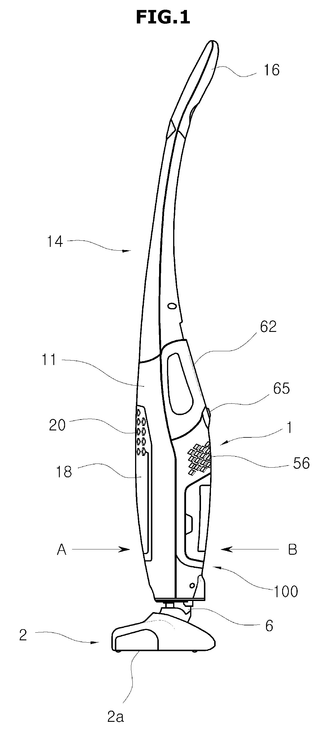
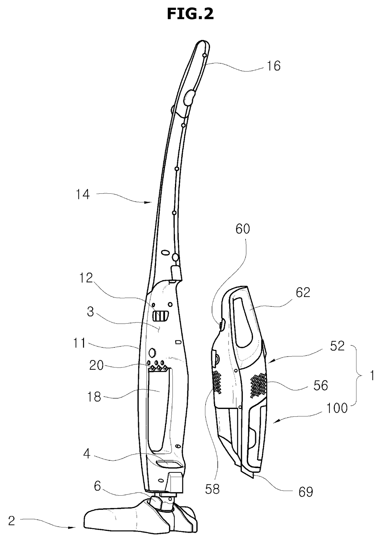
[0063]Suction units 200 and 200a in accordance with the disclosure may be applied to various types of cleaners including a canister type cleaner in which a main body and a suction nozzle are separated from each other and connected with each other through a predetermined pipe, an up-right type cleaner in which the main body and the suction nozzle are provided integrally, a hand-held type cleaner and a robot cleaner. Hereinafter, the disclosure will be described based on the hand-held type cleaner, as an example embodiment.

[0064]FIG. 1 is...


PUM


Abstract

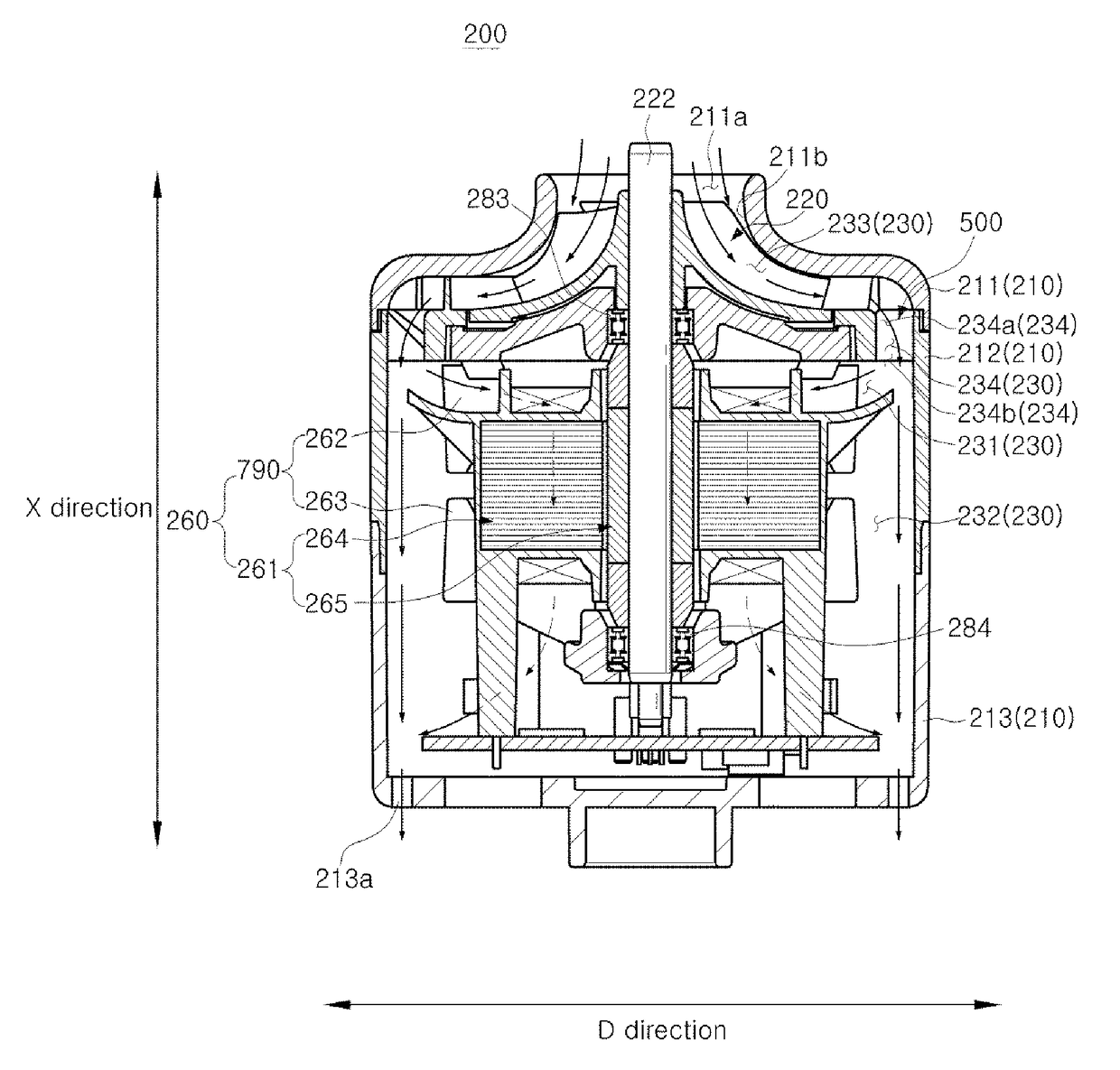
A vacuum cleaner having an improved structure capable of enhancing suction performance includes a suction unit provided in a main body, the suction unit including an impeller disposed to suck air by rotating about an axis thereof, and a diffuser disposed to guide air discharged from the impeller. The diffuser includes an inner casing, an outer casing disposed to be spaced apart from an outer circumference of the inner casing and to form a path through which the air discharged from the impeller flows, and a plurality of vanes disposed at the inner casing to guide the air discharged from the impeller to the path, and the plurality of vanes protrude toward the outer casing to cross at least a part of the path.

Description

CROSS-REFERENCE TO RELATED APPLICATIONS[0001]This application claims the priority benefit of Korean Patent Application No. 10-2014-0103133, filed on Aug. 11, 2014 in the Korean Intellectual Property Office, the disclosure of which is incorporated herein by reference.BACKGROUND[0002]1. Field[0003]Embodiments of the disclosure relate to a vacuum cleaner, and more particularly, to a vacuum cleaner having an improved structure which is capable of enhancing suction performance.[0004]2. Description of the Related Art[0005]In general, a cleaner refers to an apparatus which sucks air including dust on a surface to be cleaned, separates and collects the dust from the air, and then discharges purified air to an outside of a main body.[0006]The cleaner may include an impeller and a diffuser which are structural elements determining a suction force.[0007]The air sucked into the main body passes through the impeller and the diffuser, in turn, along a path which is bent a few times. In this proce...

Claims


Application Information

Patent Timeline
Patent Type & Authority Patents(United States)
IPC IPC(8): A47L9/00F04D29/42F04D25/08F04D29/44F04D29/62A47L5/22
CPCA47L9/0081A47L5/22A47L5/225F04D29/626F04D29/4253F04D29/444F04D25/08F05D2250/52
Inventor PARK, TAE SANGBANG, MYUNG BAEKIM, KWANG SOOPARK, JONG JINOH, HYEON JOONLEE, SEUNG YEOLIN, BYUNG RYEL
Owner SAMSUNG ELECTRONICS CO LTD
Learn More