
Lid mechanism

a technology of sliding mechanism and containing section, which is applied in the field of sliding mechanism, can solve the problems of reducing the opening area the unattractive appearance of the dual-swing container box, and the capacity of the containing section provided in the box main body, so as to reduce the opening area, enhance the appearance of the container box, and suppress the reduction of the capacity of the containing section

Active Publication Date: 2018-10-16
TOYODA GOSEI CO LTD
View PDF7 Cites 1 Cited by
  • Summary
  • Abstract
  • Description
  • Claims
  • Application Information

AI Technical Summary

Benefits of technology

The present invention provides a lid mechanism that can prevent the reduction of the container's capacity and opening area when the lid is opened. It also enhances the appearance of the container box with the lid being opened.

Problems solved by technology

This disadvantageously leads to a reduction in a capacity of a containing section provided in the box main body, and a reduction in an opening area of the container box.
This disadvantageously leads to an unattractive appearance of the dual swing container box with the lid being opened.

Method used


Image

  • Lid mechanism
  • Lid mechanism
  • Lid mechanism

Examples


first embodiment

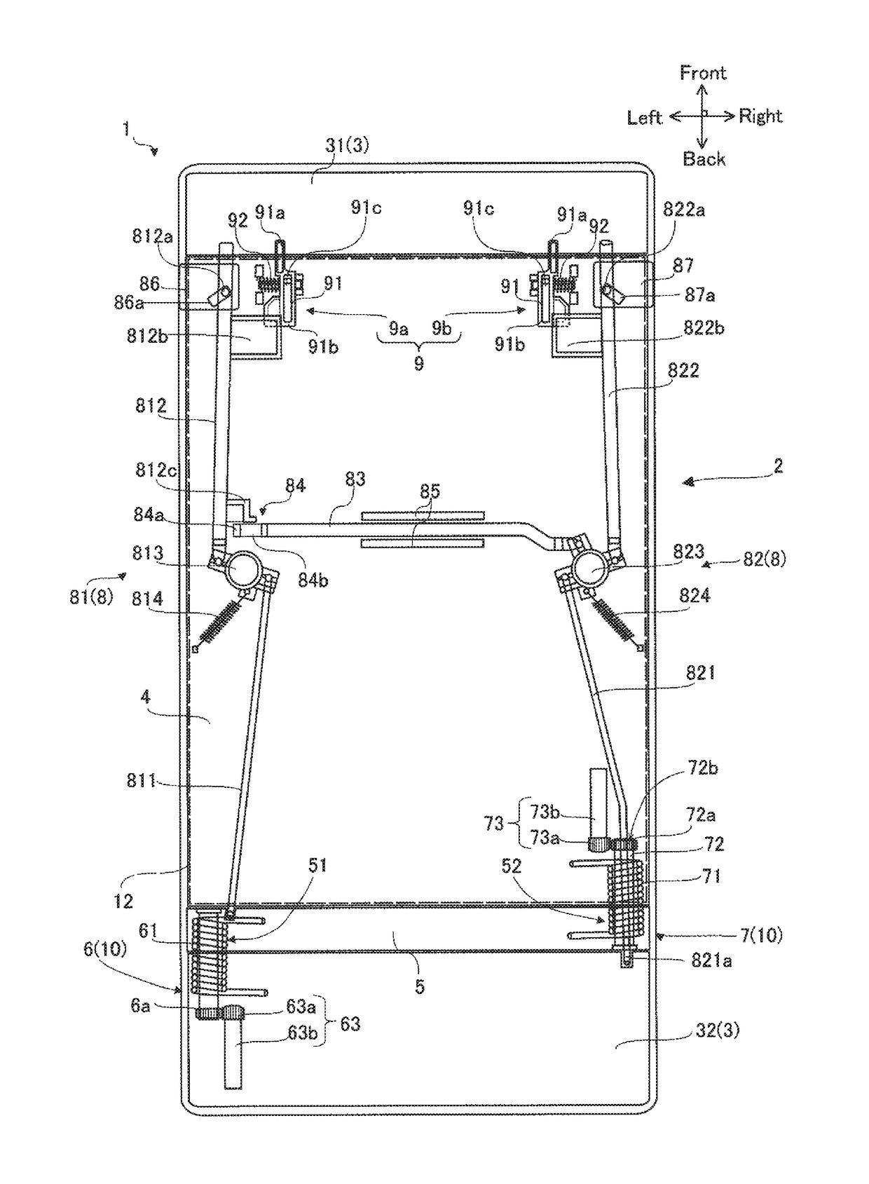
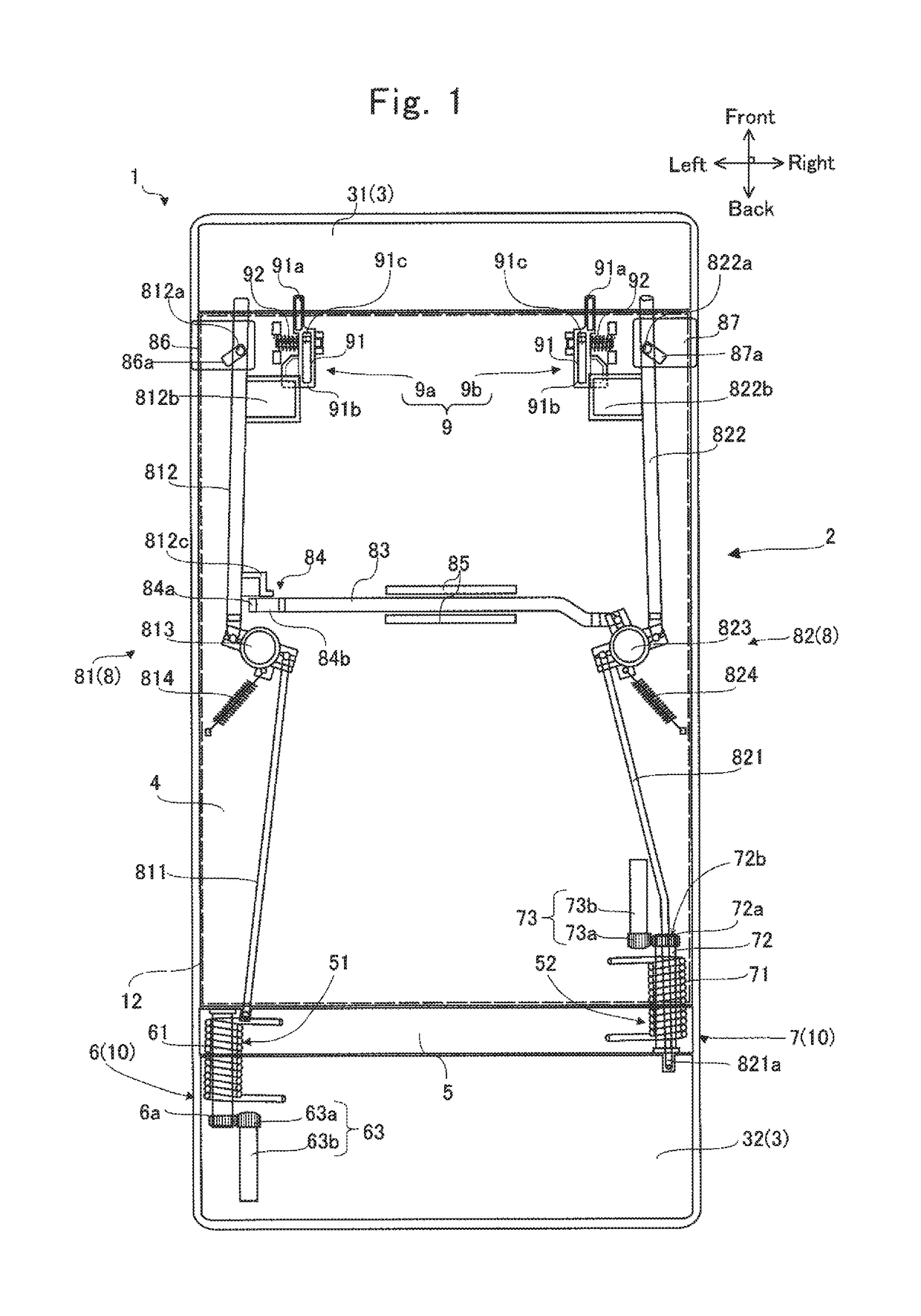
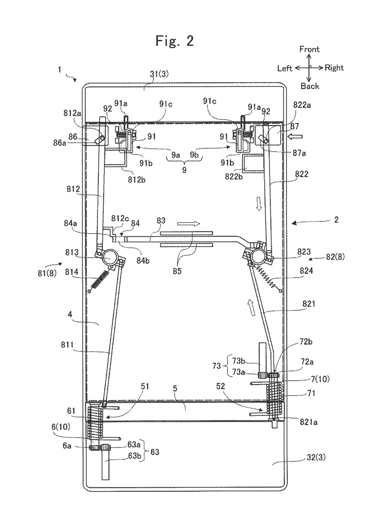
[0019]FIGS. 1 to 3 show the lid mechanism 1 according to a first embodiment, and FIGS. 4 and 5 show an example in which the lid mechanism 1 according to the first embodiment is applied to a console box 13. Furthermore, FIGS. 6 and 7 show an arm unit 53 in the lid mechanism 1 according to the first embodiment. FIG. 8 shows an alternative embodiment in which a first damper 63 and a second damper 73 according to the first embodiment are used as a swing speed-reducing element 100, as a lid mechanism 1 according to a second embodiment.

[0020]As shown in FIGS. 4 and 5, the lid mechanism 1 of the first embodiment, together with a box main body 11 having a containing section 12, configures the console box 13 disposed between a driver's seat and a passenger's seat. The box main body 11 is a box-shaped body having the containing section 12 that can accommodate articles and the like and that is open toward an upper side of a vehicle. The opening has an outer edge shape substantially the same as...

second embodiment

[0110]In the first embodiment, the swinging speed of the lid 2 is reduced by the first damper 63 or the second damper 73, but instead, a swing speed-reducing element 100 may be used. With the lid mechanism 1 in which the first damper 63 and the second damper 73 according to the first embodiment are replaced with a swing speed-reducing element 100 as a lid mechanism1 of a second embodiment, the swing speed-reducing element 100 will be hereinafter described with reference to FIG. 8.

[0111]The swing speed-reducing element 100 reduces the rotation speed of the supporting shaft 10 to reduce the swinging speed of the lid 2. The swing speed-reducing element 100 is disposed on each of the first supporting shaft 6 side and the second supporting shaft 7 side. The swing speed-reducing element 100 on the first supporting shaft 6 side reduces the rotation speed of the first supporting shaft 6, and reduces the swinging speed of the lid 2. The swing speed-reducing element 100 on the second supporti...


PUM


Abstract

A dual swing lid mechanism includes a base section and a lid openable and closable with respect to the base section. The lid includes a lid main body section, an arm section, a first supporting shaft, and a second supporting shaft. The lid main body section has a lock mechanism including a first rod engageable with the arm section and a second rod engageable with the base section. The lid changes among a closed state; a first opened state of opening a containing section with the first supporting shaft as a center; and a second opened state of opening the containing section with the second supporting shaft as the center. The first rod engages with the arm section in the closed state and the first opened state and disengages from the arm section in the second opened state. The second rod engages with the base section in the closed state and the second opened state and disengages from the base section in the first opened state.

Description

BACKGROUND[0001]1. Technical Field[0002]The present invention relates to a lid mechanism having a lid that may be opened and closed from either left or right side, and being used in a dual swing container box.[0003]2. Related Art[0004]Known container boxes for vehicles include a single swing container box disposed in a center console of a vehicle and having a lid that may be opened and closed from only one of left and right sides, and a dual swing container box having a lid that may be opened and closed from either left or right side.[0005]A dual swing container box disclosed in Japanese Unexamined Patent Publication No. 2007-245838 includes two types of arm sections for selectively opening a lid from a left side or a right side of a box main body. The two types of arm sections are respectively disposed at longitudinal ends of the box main body. Each of the arm sections includes a bias member for biasing the lid in an opening direction of the lid. When opening the lid from one side,...

Claims


Application Information

Patent Timeline
Patent Type & Authority Patents(United States)
IPC IPC(8): B65D45/00B65D43/26B65D43/22B60R7/04B60N2/75
CPCB65D43/26B65D43/22B60R7/04B65D2543/00018E05B79/12
Inventor MASATSUGU, YOSHINORIYOKOTA, NOBUHIKOFUJISAWA, HITOSHI
Owner TOYODA GOSEI CO LTD
Learn More