Panel

a technology of panels and panels, applied in the field of panels, can solve the problems of damage to the panels, pushed out of the desired position, and the known embodiment not always working smoothly, and achieve the effect of less manageability and easy installation

Active Publication Date: 2018-10-16
FLOORING IND LTD
View PDF65 Cites 3 Cited by
  • Summary
  • Abstract
  • Description
  • Claims
  • Application Information

AI Technical Summary

Benefits of technology

[0045]Further, it is noted that the locking systems of the invention are of particular interest for being applied in panels having a useful panel surface of more than 0.4 or more than 0.45 square meters. According to a particular embodiment, this concerns panels having a useful panel surface of approximately half a square meter. Herein, this may relate to oblong panels wit

Problems solved by technology

However, practice has shown that this known embodiment does not always function smoothly.
Although the locking elements disclosed there offer a compromise between vertical locking strength, by means of the rigid blocking body, and a supple coupling movement, by means of the bending zone especially provided for this purpose, such strip may cause problems during the actual coupling.
The strips known from the aforementioned documents show the disadvantage that the blocking body, during coupling in vertical direction, can be pushed out of its desired posit

Method used


Image

  • Panel
  • Panel
  • Panel

Examples


Embodiment Construction

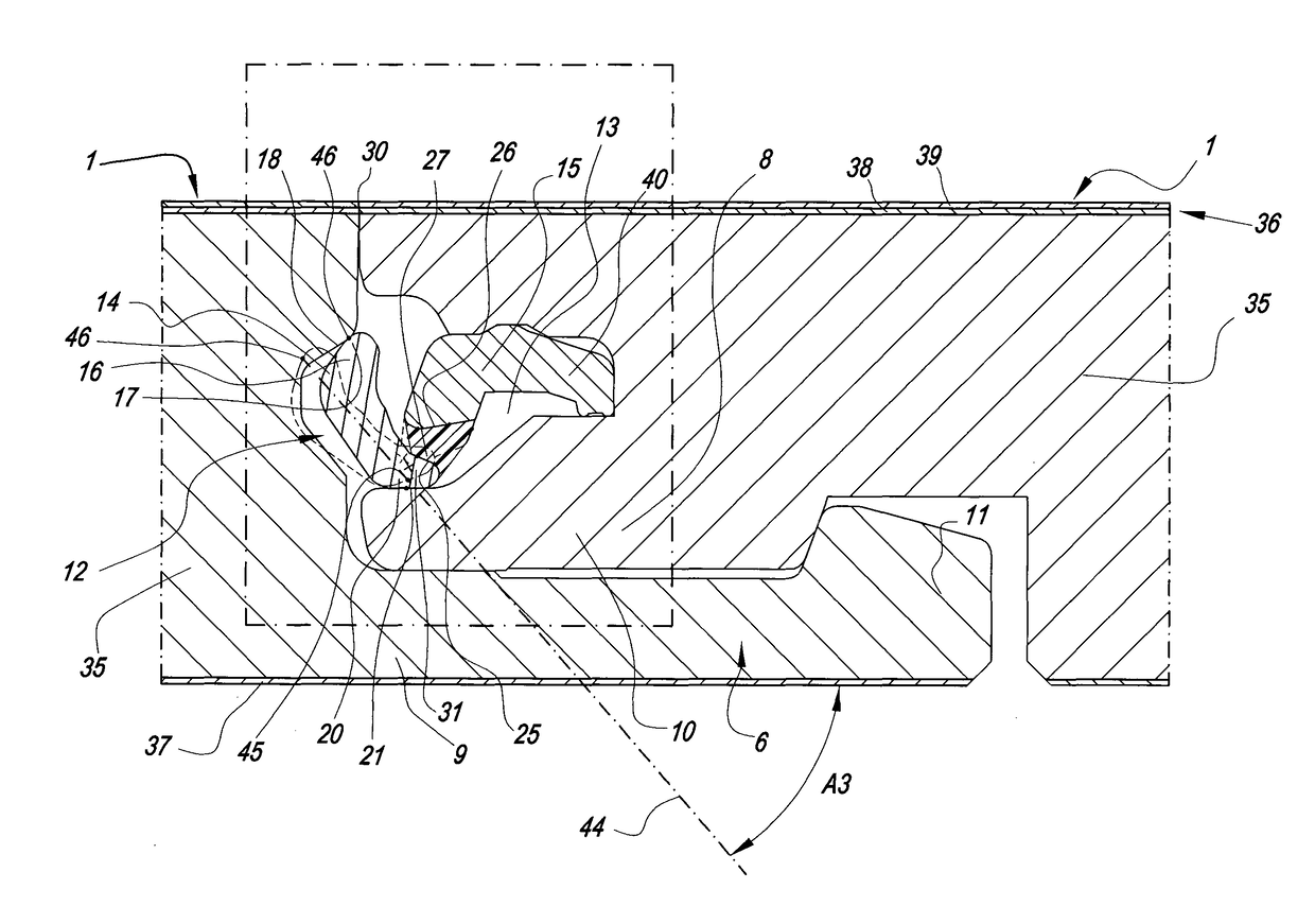
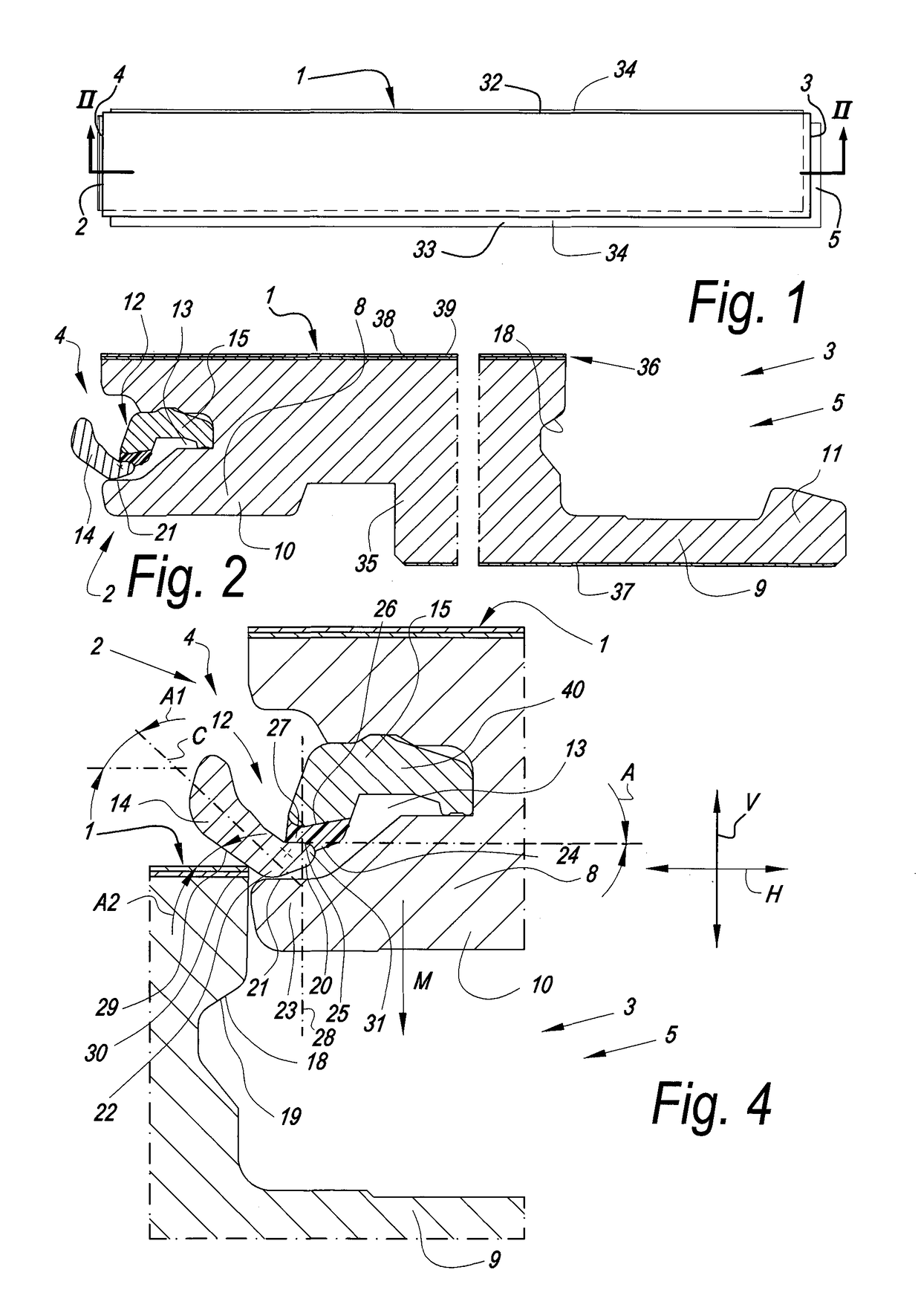
[0057]As represented in FIGS. 1 to 6, the invention relates to a floor panel 1 comprising on at least two opposite sides 2-3 coupling parts 4-5 with which two of such panels 1 can be coupled to each other.

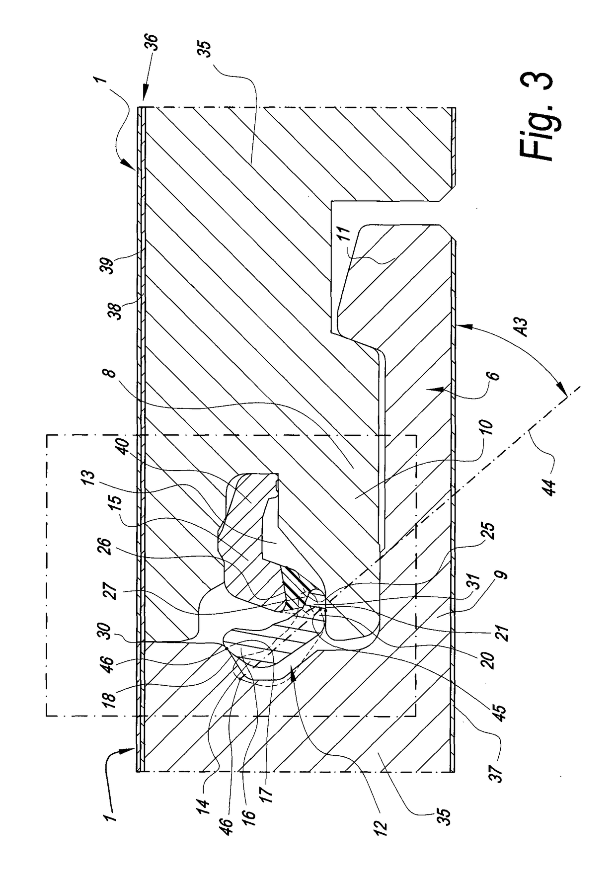
[0058]As becomes clear from the coupled condition from FIG. 3, these coupling parts 4-5 comprise a horizontally active locking system 6 and a vertically active locking system 7. The horizontally active locking system 6 comprises a male part 8 and a female part 9, which allow that two of such floor panels 1 can be connected to each other at said sides 2-3 by providing one of these floor panels 1 with the pertaining male part 8 via a downward movement M in the female part 9 of the other floor panel, which movement M is illustrated by means of the two different positions in FIGS. 4 and 5, and wherein FIG. 6 again represents the final locked position.

[0059]In the example, the male part 8 is formed by a downward-directed extremity of a hook-shaped part 10, whereas the female part 9 cons...


PUM

PropertyMeasurementUnit
Thicknessaaaaaaaaaa

Abstract

A panel includes a horizontally and vertically active locking system allowing two floor panels to be connected to each other at the sides thereof by providing one of these floor panels via a downward movement toward the other panel. The vertically active locking system comprises a locking element in the form of an insert, and the locking element comprises at least a blocking body. The blocking body is substantially or entirely made of acrylonitrile butadiene styrene (ABS).

Description

BACKGROUND OF THE INVENTION1. Field of the Disclosure[0001]This invention relates to a panel, such as, for example, to a floor panel, a ceiling panel, a wall panel or the like.[0002]More particularly, it relates to a panel comprising on at least two opposite sides coupling parts, in the form of a male coupling part and a female coupling part, respectively, which allow connecting two of such panels to each other at said sides or, in other words, can be brought in a coupled condition by providing one of these panels with the pertaining male part via a downward movement in the female part of the other floor panel, such that thereby at least a locking in horizontal direction is obtained.2. Related Art[0003]Couplings allowing that two panels, such as floor panels, can be coupled to each other by joining one floor panel with a downward movement in the other, in practice are divided into two kinds, namely a first kind where the coupling parts provide exclusively for a horizontal locking wi...

Claims


Application Information

Patent Timeline
IPC IPC(8): E04F15/02E04F15/10
CPCE04F15/02038E04F15/10E04F2201/0552E04F2201/0146E04F15/102E04F15/107E04F2201/0535E04F2201/0588
Inventor DEVOS, PIETER
Owner FLOORING IND LTD
Why Eureka
Try Eureka